No products in the cart.
Matching Stepper Motors and Drivers: A Guide for Industrial Applications
Contents
Selecting the right stepper motor and driver combination is crucial for the performance and longevity of your CNC machinery. This guide explains the essential parameters to consider, including torque, speed, voltage, and microstepping, to ensure optimal system efficiency and precision.
Mermak CNC Technical Guide
Practical notes for CNC router, automation and industrial motion systems.
Understanding Stepper Motors and Drivers for CNC
Stepper motors are indispensable in industrial automation, particularly for applications demanding precise positioning and speed control. However, their full potential is unlocked only when paired with the correct driver. The proper matching of a stepper motor and its driver is a critical engineering step that maximizes motor performance, prevents overheating, minimizes vibration, and enhances overall system efficiency. Incorrect pairings can lead to insufficient torque, missed steps, motor overheating, driver failure, or the system failing to achieve the desired precision.
This guide provides a step-by-step approach to selecting the right stepper motor and driver, offering essential technical insights for industrial buyers.
Stepper Motor Fundamentals and Technical Specifications
Stepper motors are brushless DC motors that convert digital pulses into mechanical rotational motion. Each pulse causes the motor shaft to rotate by a specific angle, known as the step angle (commonly 1.8° or 0.9°). The driver interprets these digital pulses and delivers the appropriate current and voltage to the motor’s windings, enabling rotation. The core principle of matching involves aligning the motor’s electrical and mechanical characteristics with the driver’s capabilities.
Key Motor Selection Parameters:
- Torque: This is the maximum rotational force the motor can produce. The application’s required continuous and peak torque values must be calculated, and the motor’s holding torque must exceed these figures. Dynamic torque, needed for accelerating inertial loads, should also be considered.
- Speed: The maximum angular velocity the motor needs to achieve. For high-speed applications, motors with low inductance are often preferred.
- Step Angle and Microstepping: The motor’s step angle determines positioning accuracy. The driver’s microstepping capability allows the motor’s natural step angle to be divided into smaller increments, resulting in smoother motion and higher resolution.
- Phase Current and Inductance: The motor’s nominal phase current must be compatible with the driver’s output current. Inductance affects the motor’s speed response; lower inductance motors generally achieve higher speeds but may require higher voltage drivers.
- Motor Type: Bipolar and unipolar motors are available. Bipolar motors typically offer higher torque, while unipolar motors can use simpler driver circuits. Most modern drivers support bipolar motors.
Choosing the Right Driver
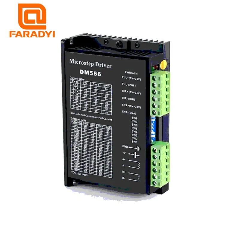
The driver is a critical component that directly influences motor performance.
- Current Capacity: The driver’s output current should match or slightly exceed the motor’s nominal phase current. Insufficient current leads to torque loss, while excessive current can cause overheating and damage. Most drivers allow for current adjustment.
- Supply Voltage: The driver’s supply voltage range must be compatible with the motor’s inductance and the desired speed. Generally, higher voltages yield better high-speed torque performance, but it’s essential not to exceed the motor’s voltage rating.
- Microstepping Capability: The driver’s microstepping options (e.g., 1/8, 1/16, 1/32) are important for achieving the required application precision.
- Protection Features: Overcurrent, overvoltage, over-temperature, and short-circuit protection enhance the longevity of both the driver and the motor.
- Control Interface: Standard interfaces include step, direction (DIR), and enable (ENA) signals. Some advanced drivers also support industrial communication protocols like Modbus or EtherCAT.
- Resonance Damping: Advanced drivers often include algorithms to reduce vibrations at the motor’s natural resonance frequencies, ensuring smoother operation and less noise.
Matching Parameters Summary:
| Parameter | Recommendation |
|---|---|
| Application Torque Requirement | Motor Holding Torque > Application Load Torque (min. 20-30% safety margin) |
| Motor Phase Current | Driver Output Current ≥ Motor Nominal Phase Current (Adjustable on driver) |
| Driver Supply Voltage | Within motor voltage limits; higher voltage for higher speeds (typically 5-20x motor nominal voltage) |
| Motor Inductance | Low inductance (1-5 mH) for high speed; high inductance (5-20 mH) for low-speed torque. Balance with driver voltage. |
| Step Angle / Microstepping | Motor step angle (e.g., 1.8°) and driver microstepping capability (e.g., 1/16, 1/32) based on application precision. |
| Motor Inertia Load | Motor rotor inertia should be at least 5-10 times the load inertia, or use an appropriate gearbox. |
| Operating Environment | Consider IP rating, temperature, and humidity for both driver and motor. |
By carefully considering these parameters, you can select a stepper motor and driver combination that ensures reliable, precise, and efficient operation for your industrial CNC router machine. For specific product recommendations or custom solutions, consult with our experts.
Ready to optimize your CNC system? Request a quote on WhatsApp today!