



































































































































Siemens SINAMICS V20 Fault Codes and Solutions
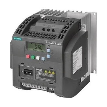
📑 Table of contents (Click to open)
Introduction and Technical Analysis
Frequency converters (or AC motor drives) are indispensable components of industrial automation, playing a critical role in motor speed and torque control. Siemens’ SINAMICS V20 series is a popular choice for small and medium-scale applications, particularly due to its cost-effectiveness, compact design, and ease of use. These drives enhance efficiency in pumps, fans, conveyors, simple machine applications, and many other industrial processes, while also offering advanced energy-saving functions (e.g., ECO mode, hibernation function). However, like any complex electronic system, SINAMICS V20 drives can occasionally experience malfunctions or faults. Rapid and accurate diagnosis and resolution of these faults are vital for minimizing production losses and ensuring operational continuity. This field guide and technical article aims to provide a comprehensive solution manual for industrial automation specialists and maintenance technicians by delving deep into Siemens SINAMICS V20 fault codes. Our goal is to accelerate on-site intervention processes, teach accurate diagnostic methods, and provide practical information to prevent recurring faults. As system complexity increases, addressing troubleshooting processes with a systematic approach is key to achieving lasting improvements rather than just temporary solutions. In this context, we will detail the potential underlying causes of each fault code and the most effective solution strategies for these causes.
Operating Principle and Technical Specifications
The Siemens SINAMICS V20 is a type of device known as a variable frequency drive (VFD) or AC motor drive. Its fundamental operating principle is to first convert the fixed voltage and frequency alternating current (AC) from the mains supply into direct current (DC) (rectifier stage), and then to convert this DC voltage back into AC at the desired voltage and frequency using pulse width modulation (PWM) technique (inverter stage). This allows for precise control of the speed and torque of a standard asynchronous motor. In addition to this basic functionality, the V20 series offers a range of advanced features that enhance energy efficiency and provide application flexibility. For example, control modes such as V/f control (voltage/frequency ratio) and quadratic V/f control provide energy savings in fan and pump applications. The integrated PID controller allows for direct control via the drive in closed-loop systems (e.g., pressure or temperature control) without the need for an external controller. Furthermore, it can be easily integrated with PLCs and other automation systems thanks to standard communication protocols like USS and Modbus RTU. Compact design, side-by-side mounting capability, and an integrated braking chopper (in certain models) optimize space within the control cabinet and reduce the need for additional hardware. The wide power range and availability of SINAMICS V20 at different voltage levels make it suitable for a diverse range of industrial applications. For these drives to operate correctly and have a long lifespan, proper installation and parameter settings according to their technical specifications are critically important. Application areas include pumps in water and wastewater treatment plants, fans in ventilation systems, conveyor belts, mixers, textile machinery, and simple machine tools. Since each application has its unique dynamics and requirements, optimizing the drive’s parameters according to these requirements makes a significant difference in both energy efficiency and system performance.
| Parameter | Value/Description |
|---|---|
| Nominal Voltage Range | 1AC 200-240V, 3AC 200-240V, 3AC 380-480V |
| Output Frequency | 0-550 Hz |
| Control Modes | V/f Control, Quadratic V/f Control, Multi-point V/f Control |
| Communication Protocols | USS, Modbus RTU |
| Protection Class | IP20 (standard) |
| Operating Temperature Range | -10°C to +40°C (up to +60°C with derating) |
| Advanced Functions | ECO Mode, Hibernation, PID Control, Automatic Restart, Flying Start |
| Overload Capacity | 150% for 60 seconds (for light-duty applications), 110% for 60 seconds (for heavy-duty applications) |
| Integrated Braking Chopper | Available in certain models. Must be checked according to manufacturer datasheet. |
Field Considerations
- Correct Installation Environment: Although SINAMICS V20 drives are designed to operate in industrial environments, environmental factors significantly impact their performance and lifespan. The temperature, humidity, dust, and vibration levels within the control cabinet where the drive is mounted must comply with manufacturer specifications. High temperatures, in particular, cause rapid aging and failure of electronic components. Ensure that the cabinet has adequate ventilation, that cooling fans (if present) operate regularly, and that air filters are not clogged. In dusty or humid environments, use cabinets with a higher IP protection rating or provide additional protection for the drive. Vibration can lead to loose connections and component fatigue, so it is important that the mounting surface is solid and vibration-free.
- Cabling Standards and Grounding: Correct cabling is critical for the safe and stable operation of the drive. Power cables (mains input, motor output) and control cables (digital input/output, analog input/output, communication) should be routed through separate channels or at a sufficient distance from each other. This minimizes electromagnetic interference (EMI/RFI). Motor cables must be shielded, and the shielding must be properly grounded at both the drive and motor ends. Shielding helps reduce high-frequency noise, protecting both the drive and other sensitive electronic devices. Grounding is vital not only for safety but also for the system’s EMI immunity. Ensure that all equipment is connected to a good central grounding point and that the grounding resistance is low. Cable cross-sections should be correctly selected according to motor current and cable length, and connections must be tight.
- Parameter Settings and Auto-tuning: The performance of SINAMICS V20 drives is directly dependent on correct parameter settings. The motor’s nameplate values such as nominal current, voltage, frequency, and speed must be accurately entered into the drive. Incorrect motor data can lead to motor overheating, triggering incorrect protection functions in the drive, or inefficient operation. In most applications, it is highly recommended to use the auto-tuning function (P1900 or P1910), which allows the drive to automatically identify the motor and determine the most suitable control parameters. This improves performance, especially in more dynamic applications requiring vector control. Acceleration and deceleration ramps should be adjusted according to the mechanical inertia and process requirements of the application. Very short ramps can lead to overcurrent or overvoltage faults, while excessively long ramps reduce efficiency. If a PID controller is used, adjusting the PID parameters (P, I, D gains) according to the process dynamics is essential for stable and accurate control.
- Periodic Maintenance and Inspections: Regular periodic maintenance is essential for the long-term and trouble-free operation of drives. Dust accumulation forms an insulating layer on electronic components, preventing cooling and leading to overheating. Therefore, it is important to clean the inside of the drive and its cooling fins with compressed air. Checking the tightness of all power and control connections prevents arc formation and voltage drops that can result from loose connections. Check that cooling fans (if present) are operating correctly and not making noise; faulty fans should be replaced immediately. Visually inspecting capacitors for signs of swelling or leakage can help detect potential faults in advance. Monitoring ambient temperature and the drive’s operating temperature provides early warning against possible overheating issues.
- Backup and Documentation: Regularly backing up drive parameters significantly shortens commissioning time in case of a fault or when a drive replacement is necessary. Parameters can be easily backed up via Siemens’ STARTER software or the BOP/BOP-2 panel. Additionally, keeping all technical documents such as the drive’s user manual, wiring diagrams, and application specifications on-site or in an easily accessible location speeds up troubleshooting and maintenance processes.
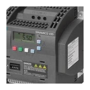
Common Issues and Solutions
Faults encountered in SINAMICS V20 drives are generally divided into two categories: fault (Fault) codes starting with “F” and warning (Alarm) codes starting with “A”. Faults are critical situations that stop the drive’s operation and require intervention. Warnings, on the other hand, are situations that indicate a potential problem but allow the drive to continue operating. In this section, we will examine the most common fault codes and their detailed solutions.
F0001 (Overcurrent):
This fault occurs when the drive’s output current exceeds the set maximum value. It is usually triggered by an instantaneous current surge.
Potential Causes:
- Short circuit or ground fault in the motor or motor cables.
- Mechanical jamming or overloading of the motor.
- Acceleration ramp set too short.
- Incorrect sizing of the drive (insufficient for motor power).
- Fluctuations or distortions in the DC bus voltage.
Solutions:
- Check the motor and motor cables (U, V, W) for short circuits or ground faults by performing an insulation test.
- Check the mechanical load of the motor, and review if there is any jamming or overloading.
- Extend the acceleration ramp (P1120). This ensures the motor accelerates slower, reducing current draw.
- Ensure motor parameters (P0304-P0307) are entered correctly and perform auto-tuning (P1900 or P1910) if necessary.
- Ensure the drive’s nominal current is appropriate for the motor current.
- Check the input mains voltage; if there are fluctuations, take corrective measures (e.g., choke coil).
F0002 (Overvoltage):
This fault is triggered when the drive’s DC bus voltage exceeds the permissible maximum value.
Potential Causes:
- Deceleration ramp set too short (motor generating regenerative energy).
- High line voltage or sudden voltage surges in the mains.
- Over-speeding of the motor (e.g., a falling load).
- Braking chopper or braking resistor being faulty/not connected (in regenerative applications).
Solutions:
- Extend the deceleration ramp (P1121). This allows the motor to decelerate slower and generate less regenerative energy.
- Check the mains voltage; rectify any abnormalities.
- Take mechanical or control measures to prevent the motor from over-speeding.
- If the application requires regenerative braking, ensure the braking chopper and braking resistor are correctly connected and functioning. If necessary, check the resistor’s value or power.
- Check DC bus voltage limits (P2172), but this parameter should generally be left at factory settings.
F0003 (Undervoltage):
Occurs when the drive’s DC bus voltage drops below the permissible minimum level.
Potential Causes:
- Voltage drop or interruption in the mains supply.
- Loose or broken connections in the drive’s input power connections.
- Blown input fuse of the drive.
Solutions:
- Measure the mains voltage and check if it is within nominal values.
- Check the drive’s input power connections (L1, L2, L3 or L, N), verify their tightness and integrity.
- Check input fuses or circuit breakers.
- If there are mains quality issues (voltage sags), consider solutions like a voltage stabilizer or UPS.
F0004 (Inverter Overtemperature):
Triggered when the temperature sensor inside the drive reaches a critical level.
Potential Causes:
- High ambient temperature.
- Drive’s cooling fan being faulty or clogged.
- Drive’s cooling fins being clogged with dust or dirt.
- Drive operating under excessive load.
- Insufficient cabinet ventilation or incorrect mounting (e.g., not leaving enough clearance for side-by-side mounting).
Solutions:
- Check the ambient temperature inside the cabinet and improve cooling if necessary (additional fan, air conditioning).
- Check if the drive’s cooling fan is operating, replace if faulty.
- Clean the drive’s cooling fins and air inlets/outlets with compressed air.
- Check the motor load, ensure the drive is not continuously operating under excessive load.
- Ensure the drive is mounted with sufficient clearance according to the mounting guide.
F0005 (Motor Overtemperature I2t):
Triggered when the drive’s internal thermal model (I2t) estimates that the motor is overheating.
Potential Causes:
- Motor operating continuously under excessive load.
- Incorrect motor parameters (P0304-P0307).
- Insufficient motor cooling.
- Motor operating above its nominal current for an extended period.
Solutions:
- Check and reduce the mechanical load on the motor.
- Ensure motor parameters are entered correctly and perform auto-tuning if necessary.
- Check that the motor’s own cooling fan is operating, clean if clogged.
- Ensure the motor operates according to its nominal current. A larger motor or drive should be considered if necessary.
F0011 (Motor Overtemperature – external sensor):
Triggered when the motor temperature exceeds the limit value via an external thermistor (PTC or KTY) or thermal sensor (P600/P601).
Potential Causes:
- Motor overheating (mechanical jamming, excessive load, insufficient cooling).
- Broken or short-circuited thermistor/sensor cables.
- Incorrect thermistor parameter settings (P0601).
Solutions:
- Check the motor temperature and eliminate the cause of overheating (reduce load, improve cooling).
- Check thermistor/sensor cables and connections.
- Ensure parameter P0601 is set for the correct sensor type (PTC, KTY84, KTY83).
- Test the sensor itself for faults.
F0022 (Auto-tuning Error):
This fault occurs when the drive fails to successfully complete motor auto-tuning (P1900/P1910).
Potential Causes:
- Motor cables not connected or incorrectly connected.
- Motor mechanically jammed or unable to rotate freely (for rotating tuning).
- Incorrect motor parameters (P0304-P0307).
- Overload or underload conditions.
Solutions:
- Ensure motor cables are correctly and tightly connected to the drive and motor.
- If rotating tuning is being performed, ensure the motor can rotate freely and is not mechanically jammed.
- Check that motor nameplate values are correctly entered into the drive.
- Try static tuning (P1900=1) if necessary.
F0070 (Communication Timeout):
This fault is triggered when the drive does not receive a command or data over the configured communication protocol (USS, Modbus RTU) within a specified time.
Potential Causes:
- Broken, short-circuited, or incorrectly connected communication cables.
- Incorrect communication parameters (address, baud rate, parity).
- Master device (PLC, HMI) stopping communication or being faulty.
- Termination resistors incorrectly or missing (especially for RS485-based Modbus/USS).
Solutions:
- Check communication cables, ensure they are correctly connected and not damaged.
- Ensure communication parameters (P2010, P2011, P2012, etc.) on the drive and master device match.
- If an RS485 network is used, ensure termination resistors (usually 120 Ohm) are correctly connected at both ends of the line.
- Check the communication status of the master device (PLC, HMI).
- Perform a power cycle on the drive and try restarting communication.
A0501 (Motor Overcurrent Warning):
Indicates that the motor current has exceeded a warning threshold before reaching the fault level. The drive continues to operate.
Potential Causes:
- Instantaneous or slight overloading of the motor.
- Acceleration or deceleration ramps not optimized.
- Motor parameters not perfectly accurate.
Solutions:
- Similar solutions to F0001 apply, but with less urgency. Check motor load, optimize ramps.
- Review motor parameters.
- Since this is a warning, it is important to monitor the general status of the system and take preventive measures to avoid future faults.
A0502 (Overvoltage Warning):
Indicates that the DC bus voltage has exceeded a warning threshold before reaching the fault level. The drive continues to operate.
Potential Causes:
- Deceleration ramp not optimized.
- Instantaneous voltage surges in the mains.
Solutions:
- Similar solutions to F0002 apply. Optimize deceleration ramps.
- Investigate the mains supply for transient overvoltage conditions.
- If regenerative braking is involved, ensure the braking resistor is correctly sized and connected.
- Monitor the application for sudden load changes that might cause regenerative energy spikes.
FAQ
What is the Siemens SINAMICS V20 drive and what are its main functions?
The Siemens SINAMICS V20 is a compact and versatile variable frequency drive (VFD) designed for basic industrial applications. It controls the speed and torque of AC motors by converting the incoming AC power to DC and then back to variable frequency AC power. Key features include energy-saving functions (ECO mode, hibernation), integrated PID control, and standard communication protocols like Modbus RTU.
What are the common causes for F0001, F0002, and F0003 fault codes on a SINAMICS V20?
F0001 (Overcurrent) is typically caused by short circuits in motor cables, mechanical motor jamming, or an acceleration ramp set too short. F0002 (Overvoltage) often results from a deceleration ramp that is too short, causing regenerative energy, or high line voltage. F0003 (Undervoltage) usually indicates a mains voltage drop or loose power connections to the drive.
How do I troubleshoot overtemperature faults like F0004, F0005, and F0011?
To resolve F0004 (Inverter Overtemperature), check the ambient temperature, ensure the cooling fan is operational and clean, and clear any dust from the cooling fins. For F0005 (Motor Overtemperature I2t), reduce the motor's mechanical load, verify motor parameters, and ensure adequate motor cooling. F0011 (Motor Overtemperature – external sensor) requires checking the motor's temperature, inspecting sensor wiring, and verifying P0601 parameter settings.
What should I do if I get an F0022 auto-tuning error?
An F0022 (Auto-tuning Error) can occur if motor cables are disconnected or incorrectly wired, the motor is mechanically jammed, or motor parameters are entered incorrectly. Ensure all motor connections are secure, the motor can rotate freely (for rotating tuning), and all motor nameplate data is accurately input. You might also try static tuning (P1900=1).
What causes an F0070 communication timeout fault and how can it be fixed?
F0070 (Communication Timeout) indicates a loss of communication between the drive and the master device (e.g., PLC). Check communication cables for damage or incorrect connections, verify that communication parameters (baud rate, address, parity) match on both devices, and ensure termination resistors are correctly installed on RS485 networks. Also, check the status of the master device.


