No products in the cart.
CNC Router for Styrofoam Cutting and 3D Modeling: Tips and Techniques

Contents
CNC Router
with Styrofoam Cutting and 3D Modeling Tips: Field Guide and Technical Article
Introduction and Technical Analysis
In today’s rapidly evolving industrial automation landscape, production efficiency and precision are paramount. Particularly in fields like prototyping, mold making, decoration, stage design, and architectural modeling, the use of lightweight and easily workable materials is becoming widespread. In this context, CNC router cutting of styrofoam (expanded polystyrene – EPS, extruded polystyrene – XPS, and similar foam materials) and 3D modeling offer revolutionary solutions in industrial applications. This technical article aims to provide a roadmap for professionals in the industrial automation sector by comprehensively covering the technical details of styrofoam cutting and 3D modeling using CNC routers, the challenges encountered in the field, and expert tips. Styrofoam’s lightness, cost-effectiveness, and ease of processing make it an ideal material for rapid prototyping and large-scale model production. However, processing this material with the correct techniques requires engineering discipline and experience to achieve the desired surface quality and dimensional accuracy. Its thermal sensitivity and low density necessitate meticulous adjustment of cutting parameters. This guide will detail how to achieve optimal results by emphasizing the integration of material science, CNC programming, and operational processes.
Principle of Operation and Technical Data
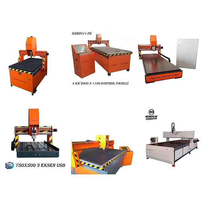
CNC router styrofoam cutting operates on the principle of converting 3D models designed in Computer-Aided Design (CAD) software into G-code via Computer-Aided Manufacturing (CAM) software, which is then processed by the CNC machine. During the machining process, a high-speed rotating cutting tool (router bit) removes material from the styrofoam block along programmed paths to create the desired shape. A primary technical challenge in processing styrofoam is its low melting point and density. Incorrectly selected cutting parameters (spindle speed, feed rate, depth of cut) can lead to material melting, sticking, or surface quality degradation. Therefore, tool selection and optimization of machining parameters are crucial. Generally, sharp-edged cutting tools that operate at high speeds and have sufficient chip clearance are preferred. Ball nose end mills are ideal for smoothly machining 3D contoured surfaces, while flat end mills are used for deep channels and flat surfaces. Tapered end mills offer advantages in machining draft-angled surfaces, especially in mold designs. Effective removal of dust and chips generated during machining improves surface quality and extends machine life. Industrial CNC routers are typically equipped with precise motion systems (linear guides, ball screws) driven by servo or stepper motors, offering high repeatability. Control systems can manage multi-axis movements simultaneously, enabling the error-free production of complex 3D geometries. CAM software determines toolpath strategies (roughing, finishing, parallel machining, spiral machining, etc.) to ensure the most efficient material processing and optimize tool life. Furthermore, simulation capabilities can detect potential collisions or errors before physical machining begins.
| Parameter | Value/Description |
|---|---|
| Material Type | EPS (Expanded Polystyrene), XPS (Extruded Polystyrene) |
| Cutter Type | Ball Nose, Flat End, Tapered End |
| Feed Rate | 2000-8000 mm/min (Adjusted based on material density and tool diameter) |
| Spindle Speed | 12000-24000 RPM (Higher speeds yield smoother surfaces) |
| Stepover | 5-15% of tool diameter (5% for finishing, 10-15% for roughing) |
| Depth of Cut | 50-100% of tool diameter (Maximum material removal per pass) |
| Cooling Requirement | Air blowing is usually sufficient; liquid cooling is not recommended. |
| Tool Material | HSS (High-Speed Steel), Carbide (Tungsten Carbide) |
Field Considerations
- Material Selection and Preparation: Styrofoam density directly impacts machining quality. Higher density styrofoam (e.g., 20-30 kg/m³) offers sharper details and smoother surfaces, while lower density materials can be machined faster but with potential detail loss. The material must be securely fixed before processing, ensuring a gap-free work surface. A firm grip using a vacuum table or mechanical clamps reduces vibration and increases dimensional accuracy. Additionally, ensuring the material is dry and at room temperature minimizes potential deformations during machining.
- Tool Selection and Toolpath Strategies: For styrofoam, use sharp-edged end mills with high helix angles and adequate chip clearance. The tool diameter should be selected based on the detail intricacy and material density. Larger diameter tools and deeper passes are used for roughing, while smaller diameter, ball nose tools and smaller stepover values are chosen for finishing. For toolpath strategy, considering the material’s thermal sensitivity, prefer strategies that keep the tool in continuous contact with the material while allowing easy chip evacuation (e.g., adaptive clearing, spiral machining).
- Optimization of Cutting Parameters: The balance between spindle speed (RPM) and feed rate is critical. Very low feed rates or very high spindle speeds can cause material melting and tool clogging. Conversely, very high feed rates or very low spindle speeds can lead to surface tearing and a rough finish. Finding optimal parameters through trial cuts is essential for every new material and tool combination. Generally, high spindle speeds and relatively high feed rates are preferred for styrofoam. Depth of cut and stepover values should be determined by balancing surface quality and machining time.
- Dust and Chip Management: Styrofoam machining generates significant dust and chips, which can damage machine components and pose health risks. Using an effective dust extraction system (vacuum) is mandatory. A suction nozzle positioned close to the machining head ensures immediate chip collection. Compressed air blowing can also aid in cooling the tool and evacuating chips, extending tool life and improving machining quality.
- Machine Maintenance and Calibration: Regular CNC router maintenance is essential for long-term, precise operation. Cleaning and lubricating moving parts (rails, screws), checking motors and drives are important. Periodic machine calibration ensures dimensional accuracy. Backlash adjustments and axis parallelism are critical factors for 3D modeling precision.
- Environmental Conditions and Safety: Styrofoam is combustible, and while the risk of sparks during machining is low, it should not be entirely disregarded. The work area must be well-ventilated, and precautions against potential fire risks should be taken. Operators must use personal protective equipment (goggles, masks, gloves). N95 or higher-rated masks are recommended to prevent inhalation of micro-particles generated during machining.
Common Problems and Solutions
Common issues encountered in styrofoam cutting and 3D modeling, along with their industrial solutions, are detailed below:
- Problem: Melting or Sticking on the Surface.
Solution: This usually occurs when the tool generates excessive heat exceeding the material’s melting point or when chips are not evacuated sufficiently. Reducing spindle speed and increasing feed rate allows the tool to remain in contact with the material for a shorter duration, reducing heat buildup. Using a sharper tool, controlling tool geometry, and ensuring continuous chip evacuation with compressed air can also resolve this issue. Tools with fewer flutes (single or double flute) compared to multi-flute tools can increase chip evacuation capacity, reducing heat buildup.
- Problem: Rough Surface Finish and Detail Loss.
Solution: Surface roughness is often related to incorrect toolpath strategy, insufficient stepover, or a dull tool. Reducing the stepover amount (e.g., 5% of tool diameter) in finishing passes, using ball nose end mills, and increasing spindle speed can improve surface finish. Ensure the tool is sharp. Using smooth entry strategies like “ramping” or “helical entry” in CAM software prevents aggressive, sudden entry of the tool into the material, thus avoiding surface damage.
- Problem: Tool Breakage or Wear.
Solution: Tool breakage typically results from overly aggressive cutting parameters (high depth of cut, low feed rate), incorrect tool selection, or foreign objects within the material. Reviewing cutting parameters and ensuring the tool is appropriate for the diameter and material prevents overloading the tool. Machining parameters should be more conservative, especially for small diameter tools. Material homogeneity should be checked, and foreign objects removed. In case of tool wear, regular tool changes or re-sharpening should be performed.
- Problem: Dimensional Deviations and Incorrect Geometry.
Solution: These issues often stem from machine calibration, backlash, workpiece fixturing problems, or errors in CAM software offsets. Periodically calibrating machine axes, checking and adjusting backlash values are important. Ensure the workpiece is securely and vibration-free fixed to the table. Tolerance settings and cutter compensation in CAM software must be configured correctly. For large parts, expansion or contraction due to temperature changes should also be considered.
- Problem: Chip Evacuation Issues and Tool Clogging.
Solution: Insufficient chip evacuation leads to tool overheating, melting, and subsequent clogging. Using a powerful dust extraction system and ensuring the tool’s geometry is suitable for chip evacuation is essential. Especially when machining deep pockets or narrow areas, the tool must have sufficient space to expel chips from the surface. If necessary, short pauses can be added between machining steps for tool cleaning, or continuous cleaning can be provided with compressed air jets.
Expert Advice
CNC router cutting and 3D modeling of styrofoam is an indispensable technology offering fast, cost-effective, and high-precision production capabilities in industrial automation processes. With a wide range of applications from prototyping to final product molds, this method can yield results beyond expectations when applied with the right knowledge and experience. A successful machining process requires in-depth knowledge of material science, tooling technology, CAM programming, and machine operation. Styrofoam’s unique thermal and mechanical properties, in particular, demand special approaches beyond standard machining parameters. For industrial automation professionals, staying abreast of continuous developments and innovations in this field is critical for achieving optimized workflows and competitive advantages. Next-generation CAM software, AI-driven toolpath optimizations, and sensor integrations will further enhance the efficiency and error-freeness of styrofoam machining processes. Remember that every new project is an opportunity for learning and optimization. Combining trial-and-error with a scientific approach, analyzing the data obtained, and continuously improving processes are key to achieving expertise. Adherence to safety standards, regular machine maintenance, and the use of quality consumables are foundational for long-term success. We hope this comprehensive guide assists industry engineers and technicians in overcoming field operational challenges and elevating their styrofoam machining capabilities. In the future, with smarter and more integrated production systems, the application areas and processability limits of styrofoam will expand even further.