



































































































































Optimizing CNC Plexiglass Cutting Parameters: Spindle Speed and Feed Rate
📑 Table of contents (Click to open)
Introduction and Technical Analysis
In industrial automation and manufacturing sectors, CNC (Computer Numerical Control) machines have become an indispensable part of precise and repeatable production processes. Specifically, the cutting of thermoplastic materials like plexiglass (PMMA – Polymethyl Methacrylate) has a wide range of applications due to its aesthetic appearance, lightness, and durability. Used in many fields such as advertising, lighting, architectural applications, machine guards, and sign manufacturing, the surface quality, edge smoothness, and dimensional accuracy achieved in CNC cutting of plexiglass are directly dependent on the selected cutting parameters. Foremost among these parameters are spindle speed (RPM – Revolutions Per Minute) and feed rate (mm/minute). Determining the correct combination of spindle speed and feed rate is a critical engineering task that directly affects not only product quality but also tool life, machine efficiency, and material waste. Incorrect parameters can lead to undesirable results such as material melting, sticking, cracking, edge whitening, or premature tool wear. This field guide and technical article aims to provide guidance to industrial automation specialists and operators by detailing the fundamental principles, technical data, and practical applications behind the selection of spindle speed and feed rate in CNC plexiglass cutting.
Operating Principle and Technical Data
The basic operating principle in CNC plexiglass cutting relies on a rotating cutting tool (router bit) removing material from a stationary or moving workpiece. Since plexiglass is a thermoplastic material, heat management during cutting is vitally important. Reaching temperatures close to the material’s melting point can cause the material to stick to the cutting tool, leave melt marks on the edges, or cause whitening. Therefore, spindle speed and feed rate parameters are adjusted to optimize heat generation by directly controlling the contact time between the tool and the material, and the amount of material removed per unit time (chip load).
Spindle Speed (RPM): Spindle speed indicates how many revolutions the cutting tool makes per minute. High RPM generally offers the potential for achieving a smoother surface finish because each tooth of the tool contacts the material more frequently. However, with thermoplastic materials like plexiglass, very high RPM can lead to excessive heat buildup due to friction, causing the material to melt. This situation prevents the evacuation of molten plexiglass chips sticking to the tool surface and reduces cutting quality. The optimal RPM varies depending on the tool diameter, number of flutes, and material thickness. Generally, smaller diameter tools operate at higher RPMs, while larger diameter tools are preferred at lower RPMs.
Feed Rate: Feed rate refers to the distance (mm/minute) the cutting tool travels over the workpiece in one minute. The feed rate is directly related to the chip load (fz). Chip load indicates how much material each tooth of the tool removes per revolution and is expressed in millimeters/tooth (mm/tooth). The chip load formula is as follows: fz = Feed Rate / (Spindle Speed x Number of Flutes). Chip load is a critical parameter in plexiglass cutting. A very low chip load (i.e., low feed rate or very high RPM) causes the tool to “rub” the material, leading to excessive heat generation and melting. On the other hand, a very high chip load (i.e., high feed rate or very low RPM) puts excessive stress on the tool, causing tool breakage, material cracking, or leaving a rough surface on the edges. For plexiglass cutting, single-flute (O-flute) or two-flute (up-cut/down-cut) carbide router bits are generally preferred. Single-flute router bits, in particular, facilitate chip evacuation and reduce heat buildup.
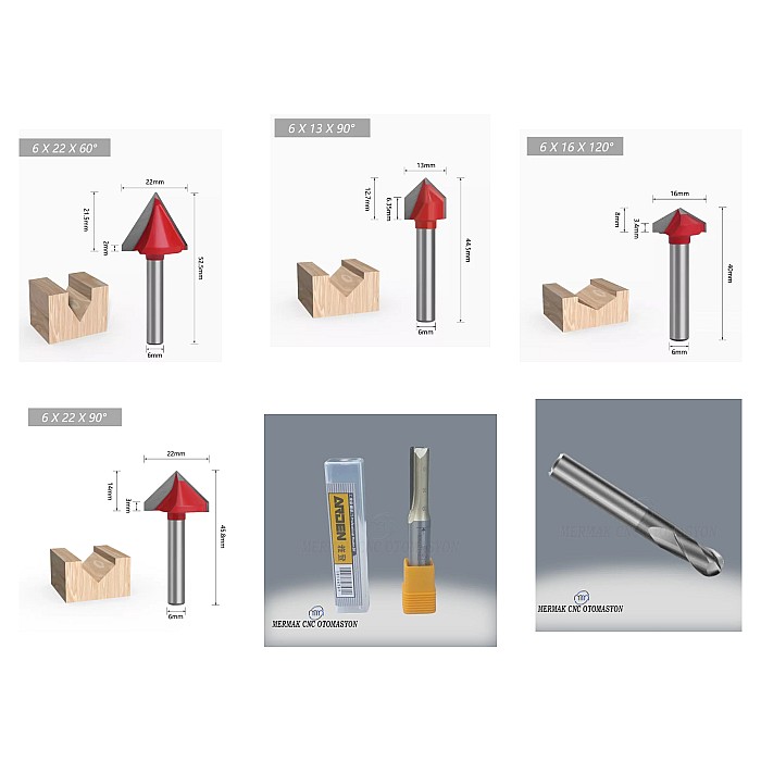
Tool Selection: Router bits used for plexiglass cutting are generally referred to as single-flute (O-flute) or two-flute. Single-flute router bits optimize chip evacuation and reduce heat, especially at high speeds and deep cuts. Up-cut router bits eject chips upwards, while down-cut router bits push chips downwards, providing a cleaner cut on the top surface. However, chip evacuation on the bottom surface can become difficult. Compression router bits are designed to provide clean cuts on both the top and bottom surfaces, but they are more expensive and require more precise parameter settings.
Cooling: Cooling is important in plexiglass cutting to prevent heat buildup. Generally, air blast is sufficient. Air both cools the cutting area and helps evacuate chips. In some cases, especially with thick materials or aggressive cuts, mist cooling (liquid spray) can be used, but care must be taken to ensure it does not leave residue on the plexiglass.
Material Thickness and Cutting Strategy: Material thickness directly affects cutting parameters. For thicker plexiglass, multi-pass cutting should be preferred over a single pass. By removing less material with each pass, heat buildup is controlled, and the load on the tool is reduced. The depth of each pass should not be less than half of the tool diameter, but should not exceed the tool diameter. Generally, passes with a depth of 50-70% of the tool diameter yield good results.
| Parameter | Value/Description |
|---|---|
| Material Type | Acrylic (PMMA) – Cast or Extruded |
| Tool Type | Single-Flute (O-Flute) Carbide Router Bit, Up-Cut |
| Tool Diameter (D) | 3 mm |
| Material Thickness | 3 mm – 10 mm |
| Spindle Speed (RPM) | 18,000 – 24,000 RPM (For smaller diameters: 24,000-30,000 RPM) |
| Feed Rate (mm/minute) | 500 – 1500 mm/minute (Adjust according to tool diameter and RPM) |
| Chip Load (fz) | 0.05 – 0.15 mm/tooth (Must be tested for optimum values) |
| Depth of Cut (Ap) | 50% – 70% of tool diameter (e.g., 1.5 – 2.1 mm for a 3mm tool) |
| Cooling Method | Air Blast or Mist Cooling |
| Radial Depth of Cut (Ae) | Full tool diameter (D) (for contour cutting) |
Field Considerations
- Tool Runout and Vibrations: Even the slightest runout in the spindle motor or tool holder negatively affects cutting quality and shortens tool life. Runout can lead to breakage, especially with thin router bits. Periodically check spindle and tool holder precision; tools must be installed and tightened correctly. Vibrations can cause roughness on cutting edges and material cracking. Machine rigidity and workpiece clamping methods should be checked.
- Workpiece Clamping (Fixturing): The plexiglass sheet must not move during cutting. Vacuum tables, mechanical clamps, or double-sided tape combinations can be used. Insufficient clamping leads to vibrations, tool breakage, and dimensional errors. Especially when cutting small parts, ensure sufficient vacuum power.
- Material Quality and Type: Plexiglass comes in two main types: cast and extruded. Cast plexiglass is more rigid and generally has better optical quality but is more brittle. Extruded plexiglass is more flexible and more affordable, but it may have higher internal stresses. These differences can affect cutting parameters; extruded plexiglass often requires lower chip loads and more careful heat management. Internal stresses in the material can lead to cracking after cutting.
- Chip Evacuation: Effective removal of chips from the cutting zone is key to preventing heat buildup and tool clogging. Single-flute router bits and air blast are critically important given the sticky nature of plexiglass chips. Insufficient chip evacuation leads to overheating of the tool and melting of the material.
- Test Cuts and Optimization: Performing a small test cut for each new material batch, tool, or project is the most reliable method to find the optimal parameters. The starting values provided are a reference point. Spindle speed and feed rate should be fine-tuned by observing the smoothness of the cutting edge, the absence of melt marks, the sound of the tool, and the condition of the chips. Chips should generally be transparent and small, not turn into dust or melt and stick.
- Tool Condition and Sharpness: A dull or damaged tool will rub the plexiglass instead of cutting it, generating excessive heat, which leads to melting and poor surface quality. Tools should be regularly inspected and replaced when necessary. A sharp tool produces lower cutting forces and less heat.
Common Problems and Solutions
1. Problem: Melting, Sticking, or Whitening on Plexiglass Edges
Causes: This is one of the most common problems. It usually results from excessive heat buildup due to very high spindle speed, very low feed rate (low chip load), insufficient chip evacuation, or a dull tool.
Solutions: Gradually reduce the spindle speed or increase the feed rate to raise the chip load. Ensure you are using a single-flute (O-flute) carbide router bit. Enhance chip evacuation with an air blast. Check the sharpness of the tool; replace it if necessary.
2. Problem: Cracking, Breakage, or Roughness (Chipping) on Plexiglass Edges
Causes: Very high feed rate (high chip load), very low spindle speed, insufficient workpiece clamping, tool runout, or material internal stresses.
Solutions: Gradually reduce the feed rate or increase the spindle speed. Ensure the workpiece is securely clamped. Check and eliminate tool runout. Review material quality (especially for extruded plexiglass); consider using cast plexiglass if necessary. Try less aggressive cutting parameters (smaller depth of cut).
3. Problem: Tool Breakage
Causes: Very high feed rate, excessively deep pass, incorrect tool selection (e.g., too thin a tool), tool runout, insufficient chip evacuation (tool clogging), or collision.
Solutions: Reduce the feed rate and decrease the depth of cut. Select the tool diameter and type appropriate for the application. Check for tool runout. Optimize chip evacuation. Perform checks in the CNC program to eliminate the risk of collision.
4. Problem: Dimensional Errors or Rounding in Corners
Causes: Machine calibration issues, tool runout, workpiece movement, excessive tool deflection (especially with long and thin tools), or incorrect tool compensation.
Solutions: Check the calibration of the machine axes. Eliminate tool runout and ensure the workpiece is securely clamped. Use a shorter or more rigid tool if necessary. Check tool compensation settings in the CNC program.
5. Problem: Ripples or Lines on the Cut Surface
Causes: Tool vibrations, runout in the spindle or tool holder, dull tool, insufficient machine rigidity, or incorrect tool path strategy (e.g., too fast turns).
Solutions: Check and eliminate tool runout. Check the sharpness of the tool. Evaluate the general condition and rigidity of the machine. Try reducing tool path speeds slightly, especially around sharp turns.
Expert Advice
Achieving the best results in CNC plexiglass cutting is a dynamic process that requires skillfully balancing spindle speed and feed rate parameters. This balance relies not only on theoretical knowledge but also on practical understanding developed through field experience, continuous observation, and trial-and-error. It should be noted that every industrial CNC router machine, every tool, and even every batch of plexiglass sheets can react differently. Therefore, the values and methodologies mentioned above should be considered a starting point, but final optimization must always be done according to specific application conditions. As industrial automation specialists, you should aim for continuous improvement in your production processes, carefully analyze the results obtained from each cut, and adjust your parameters based on this feedback. Selecting a quality router bit, proper workpiece clamping, effective chip evacuation, and regular tool inspection are success factors as critical as the parameters themselves. Although it may require some time and effort initially, determining optimal parameters will extend tool life, minimize material waste, and enable you to produce superior quality products that will give you a competitive edge in the market. This guide provides a solid foundation for overcoming challenges in CNC plexiglass cutting and perfecting your production processes. The path to success lies in attention to detail and a continuous desire to learn.
FAQ
What are the recommended spindle speeds (RPM) for cutting plexiglass on a CNC router machine?
For CNC plexiglass cutting, the optimal spindle speed typically ranges from 18,000 to 24,000 RPM for a 3mm tool. For smaller diameter tools, speeds between 24,000 and 30,000 RPM might be necessary. It's crucial to balance this with the feed rate to prevent overheating and melting, which are common issues with thermoplastic materials.
What is the appropriate feed rate for cutting plexiglass with an industrial CNC router?
The ideal feed rate for CNC plexiglass cutting usually falls between 500 and 1500 mm/minute, depending on the tool diameter and spindle speed. This parameter directly influences the chip load. A chip load of 0.05 – 0.15 mm/tooth is often a good starting point, but fine-tuning through test cuts is essential to achieve the best edge quality and prevent material issues like melting or chipping.
Which type of router bit is best for CNC plexiglass cutting?
Single-flute (O-flute) carbide router bits are highly recommended for plexiglass. Their design facilitates efficient chip evacuation and reduces heat buildup, which is critical for thermoplastic materials. Up-cut bits are common, but down-cut or compression bits can be used for specific surface finish requirements.
What are the most common issues encountered during CNC plexiglass cutting and how can they be resolved?
Common problems include melting or whitening of edges (due to high RPM, low feed rate, or dull tool), cracking or chipping (due to high feed rate, low RPM, or poor clamping), and tool breakage (due to excessive load or wrong tool). Solutions involve adjusting spindle speed and feed rate, ensuring proper chip load and evacuation, using sharp tools, and secure workpiece clamping.
How important is cooling and cutting strategy for successful plexiglass machining?
Effective cooling, typically air blast, is vital to prevent heat buildup and facilitate chip evacuation. For thicker materials or aggressive cuts, mist cooling might be considered, but ensure it doesn't leave residue. Multi-pass cutting is also recommended for thicker plexiglass to manage heat and reduce tool stress.


