
No products in the cart.
%42 Discount


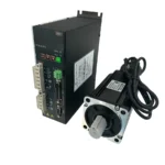
750W Servo Motor Set 80ST-M02430 T3L-L20F-RABN
Original price was: 558.28$.323.21$Current price is: 323.21$.
Best Quality, Best Price Guarantee
In stock
🔥 Special for Today Only %42 Discount Opportunity!📦 Category: 80 Flange Servo Motors🏷️ Power: 0.75 kW🏷️ Operating Voltage: 220 V AC🏷️ Flange Size: 80 mm🏷️ Brake Configuration: Standard🏷️ Maximum Speed: 3000 RPM
Mermak assuranceFrom factory to end user · importer / main dealer · strong stock
ImporterMain dealer / distributorStrong stockGood priceCorporate invoice
In stock / available to order · 14-day return for standard unused products; conditions may vary for custom size/cut products.
750 Watt Servo Motor Set 80ST-M02430 T3L-L20F-RABN
INDUSTRIAL AUTOMATION PARTS | SUPERIOR PERFORMANCE SERIES
Detailed Product Review
This 750W AC servo motor set is a high-performance electromechanical drive solution designed to provide precise motion control in industrial automation systems. The core components of the set are the synchronous AC servo motor with model code 80ST-M02430 and the servo driver with model code T3L-L20F-RABN, which is fully compatible with this motor. The motor continuously transmits the angular position, speed, and torque feedback of the rotor to the servo driver via its integrated 2500 PPR (Pulses Per Revolution) incremental encoder. This closed-loop control principle allows the driver to sense the motor’s instantaneous state and reach the desired position, speed, or torque values within milliseconds through its control algorithm, maximizing the system’s dynamic response and repeatability. Especially in applications requiring millimeter precision and high repeatability, the control accuracy offered by this set is a critical factor directly impacting the quality and efficiency of production processes.
The motor’s material structure is manufactured using high-strength alloys and an optimized magnetic circuit design, enabling it to achieve impressive performance values such as a rated torque of 2.4 N·m and a rated speed of 3000 RPM. Its capability to reach a maximum speed of 6000 RPM offers flexibility in processes requiring fast cycle times. For ease of system integration, it features a standard 80 mm x 80 mm flange size and a 19 mm shaft diameter, ensuring compatibility with various gearboxes and couplings. The IP65 protection class indicates that the motor is completely sealed against dust ingress and protected against low-pressure water jets from all directions; this feature is critical for ensuring uninterrupted and reliable operation even in harsh industrial environmental conditions, such as in machining workshops or humid production lines. The set includes 10-meter power and encoder cables, along with a +5V or +24V signal cable, providing all necessary connection components for a complete installation, eliminating the need for additional parts and accelerating the commissioning process. This comprehensive structure offers an ideal solution for high-performance motion control in a wide range of applications, including CNC machines, industrial robotic systems, conveyor belts, assembly lines, and packaging machines.
Advantages of the 750 Watt Servo Motor Set 80ST-M02430 T3L-L20F-RABN
High-Resolution and Repeatable Positioning: The integrated 2500 PPR (Pulses Per Revolution) incremental encoder generates 2500 pulses per revolution of the motor, providing high-resolution feedback to the driver. This enables millimeter-level precise positioning in closed-loop control systems and accurate position information at all times during motion. Especially in critical operations like cutting depth, tool path tracking in CNC machines, and object manipulation in robotic applications, this high resolution minimizes repeatability errors and elevates production quality standards. The high signal quality of the encoder also increases its resistance to electrical noise, ensuring a stable feedback signal.
Wide Dynamic Operating Range and High Speed Response: This servo motor set offers continuous high performance with a rated torque of 2.4 N·m and a rated speed of 3000 RPM, while also having the capacity to reach maximum speeds of up to 6000 RPM for short-term operations. This wide dynamic range allows the system to perform precise and controlled movements under heavy loads and maintain rapid acceleration and deceleration capabilities in applications requiring fast cycle times. In scenarios such as rapid traverse movements in CNC machines or high-speed product transfers on packaging lines, the motor’s high torque and speed dynamics provide operational flexibility without compromising efficiency. The optimized rotor inertia ensures minimal delay in rapid start-stop cycles.
Superior Durability Against Harsh Industrial Environmental Conditions: The motor’s IP65 protection class indicates a high level of protection against solid objects and water according to international standards. The digit ‘6’ signifies that the motor is completely dust-tight, meaning no dust particles can penetrate the motor. The digit ‘5’ indicates that the motor is protected against low-pressure water jets from all directions; this prevents damage to the motor’s internal components even when exposed to light water splashes or humid environments. This feature guarantees long-lasting, reliable, and uninterrupted operation of the motor in demanding industrial conditions such as machining, food processing, chemical production, or outdoor applications. Furthermore, the motor’s built-in overvoltage, undervoltage, overload, and overcurrent protection mechanisms provide an additional layer of safety against electrical fluctuations and operational errors, enhancing the overall durability of the system. We proudly supply to countries including the United Kingdom, United States, Canada, Australia, Ireland, New Zealand, and South Africa, as well as similar international markets.
Technical Specifications and Capacity
FeatureValue/Description
Motor Power750W (Continuous power output, optimized for high dynamic performance.)
Rated Torque2.4 N·m (Continuous torque value under nominal operating conditions, strong load-carrying capacity.)
Rated Speed3000 RPM (Optimum efficiency and control precision at nominal operating speed.)
Maximum Speed6000 RPM (Flexibility for short-term high-speed operations and rapid start-stop capability.)
Encoder Type2500 PPR incremental (Precise position and speed control with high-resolution feedback.)
Protection ClassIP65 (Complete protection against dust ingress and low-pressure water jets from all directions.)
Set Contents1 Servo Motor, 10m Power Cable, 10m Encoder Cable, +5V/+24V Signal Cable.
Technical Frequently Asked Questions (FAQ)
How should the inertia ratio be optimized in the driver settings of this servo motor set?
The inertia ratio in servo motor systems is defined as the ratio of load inertia to motor rotor inertia and critically affects the system’s dynamic response and stability. As a general rule, it is recommended to keep this ratio between 1:1 and 1:10 for optimal performance; however, the ideal value may vary depending on the required acceleration/deceleration times, vibration tolerance, and positioning accuracy of the application. A load inertia significantly higher than the motor inertia (e.g., above 1:20) can increase the system’s response time, lead to overheating, and cause oscillations in the control loop. To minimize this, the driver’s automatic tuning functions should be used, or PID (Proportional-Integral-Derivative) gain values should be adjusted manually. Proper adjustment of acceleration and deceleration ramps is crucial for ensuring stable system operation and reducing mechanical stress. If necessary, using a gearbox or selecting a motor with higher inertia should be considered to reduce the inertia ratio.
How does backlash or flexibility in the mechanical system connected to the servo motor shaft affect positioning accuracy, and how can this be minimized?
Backlash in mechanical systems refers to the unwanted play in transmission elements such as gearboxes, couplings, or ball screws that occurs when the direction of motion changes. This backlash causes the feedback signal from the servo motor’s encoder to not accurately reflect the actual position of the motor shaft, directly negatively impacting positioning accuracy. Especially in CNC machining or robotic assembly applications requiring high precision, backlash can lead to delays or deviations in the tool or robot end-effector reaching the desired position. To minimize this effect, low-backlash planetary gearboxes or backlash-free couplings should be preferred first. Additionally, preloading in linear transmission elements like ball screws is an effective way to reduce backlash. Servo drivers often have a “backlash compensation” feature that can help compensate for this play in software, but the best results are achieved by physically minimizing mechanical backlash. Flexibility in the system arises from the deformation of mechanical components under load, which can also lead to positioning errors; this should be addressed with more rigid materials and structural designs.
The power and encoder cables for this 750W servo motor set are specified as 10 meters long. What technical issues might arise regarding signal integrity and power loss if longer cables are used?
Cable length is a critical parameter in servo motor systems, affecting both power transmission and signal integrity. The standard 10-meter cable length is optimized considering the motor’s rated current (3.5A) and encoder signal levels. Using longer power cables will increase cable resistance, leading to voltage drop, which can prevent the motor from operating at its nominal voltage, causing performance loss, reduced torque, and overheating. Furthermore, increased cable length can heighten susceptibility to electrical noise (EMI/RFI). For encoder cables, signal attenuation and susceptibility to external electromagnetic interference significantly increase with length. This can lead to distortion of the high-frequency pulse signals from the encoder, incorrect position information being perceived, and consequently, instability or error messages in the control system. To prevent such issues, when longer cable lengths are needed, thicker power cables and high-quality, shielded encoder cables should be used, and methods like signal repeaters or differential signal transmission should be considered. Proper grounding of cables and routing them separately from other power cables are also essential for maintaining signal integrity.
What are the technical advantages and disadvantages of using an absolute encoder instead of the incremental encoder in this servo motor set?
The 2500 PPR incremental encoder used in this set measures the motor’s movement with pulse signals, where each pulse represents a specific angular displacement. When the system loses power and is turned back on, the incremental encoder loses its initial position and requires a homing procedure to return to a reference point. This can extend restart times, especially in multi-axis or complex automation systems. Absolute encoders, on the other hand, generate a unique digital code for each angular position, retaining the motor’s position in memory even after a power interruption. This allows the system to have the correct position information immediately upon restart, eliminating the need for a homing process and significantly reducing machine downtime, thereby increasing operational efficiency. Technical advantages include faster startup, error tolerance, and more reliable position tracking in complex motion sequences. However, absolute encoders are generally more expensive than incremental encoders and may require more complex connection interfaces (e.g., SSI, BiSS, EnDat). Additionally, the resolution of absolute encoders may not be as high as some incremental encoders, although this is increasingly being overcome with modern absolute encoder technologies. Depending on the application requirements, the encoder type should be selected considering the balance between cost, speed, and accuracy.
| Power | 0.75 kW |
|---|---|
| Operating Voltage | 220 V AC |
| Flange Size | 80 mm |
| Brake Configuration | Standard |
| Maximum Speed | 3000 RPM |
| Torque | 2.4 Nm |
| Encoder Resolution | Incremental 2500 PPR |
You must be logged in to post a review.
Taksit Tablosu
Related Products
 %42 Discount1kW Servo Motor Set 80AST-A1C04025 T3D-L20A-RABFOriginal price was: 408.04$.236.23$Current price is: 236.23$.View
 %68 Discount0.75 kW Siemens SINAMICS V20 Variable Frequency Drive (VFD) - 220V Single Phase InputOriginal price was: 365.86$.118.08$Current price is: 118.08$.View
 %60 Discount5.5 kW 220V to 380V Motor Drive InverterOriginal price was: 713.09$.285.24$Current price is: 285.24$.View
Reviews
There are no reviews yet.