



































































































































What is a Relay Board? Controlling Water Pumps and Vacuum Motors in CNC Machines
📑 Table of contents (Click to open)
- What is a Relay Board? Introduction and Technical Analysis of Water Pump and Vacuum Motor Control in CNC Ma...
- What is a Relay Board? Operating Principle and Technical Data for Water Pump and Vacuum Motor Control in CN...
- What is a Relay Board? Field Considerations for Water Pump and Vacuum Motor Control in CNC Machines
- What is a Relay Board? Common Problems and Solutions for Water Pump and Vacuum Motor Control in CNC Machines
- What is a Relay Board? Conclusion and Expert Advice for Water Pump and Vacuum Motor Control in CNC Machines
- FAQ
What is a Relay Board? Introduction and Technical Analysis of Water Pump and Vacuum Motor Control in CNC Machines
At the heart of industrial automation systems, particularly in precision manufacturing platforms like CNC machines, relay boards are indispensable components for safely and efficiently switching high-power electrical loads with low-power control signals. This technical article and field guide will comprehensively cover relay boards, starting from their fundamental operating principles, their importance in controlling industrial loads such as water pumps and vacuum motors in CNC machines, technical details, field applications, and solutions for potential problems. Our goal is to provide industry professionals, engineers, and technicians with an in-depth understanding of this critical technology. Relay boards act as a bridge, opening and closing the main power circuits that feed kilowatt-level motors, heaters, or other actuators, using millivolt-level signals from a PLC (Programmable Logic Controller), microcontroller, or CNC control unit. This isolation and power amplification capability not only protects the sensitive electronic components of the control circuit from high voltage and current fluctuations but also enhances operator safety. Especially in CNC machines, the precise and reliable switching of cutting fluid pumps or vacuum motors that control the vacuum table is vital for production quality and efficiency. In this context, correct relay board selection, proper installation, and regular maintenance directly impact the system’s overall performance and lifespan.
What is a Relay Board? Operating Principle and Technical Data for Water Pump and Vacuum Motor Control in CNC Machines
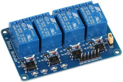
A relay board is an electronic module that typically houses multiple relays on a single PCB (Printed Circuit Board) and is designed for easy integration with control systems. Fundamentally, a relay is a switch controlled by a low-power electrical signal. This switch can open or close a higher-power circuit. Relays are primarily divided into two categories based on their switching principles: electromechanical relays and solid-state relays (SSR).
Operating Principle of Electromechanical Relays: These types of relays consist of a coil, an armature, a spring, and a set of electrical contacts. When a control signal is applied to the coil, the coil generates a magnetic field. This magnetic field attracts the armature, moving the contacts attached to it. The movement of the contacts opens (normally open – NO contacts close) or closes (normally closed – NC contacts open) the main power circuit. When the control signal is removed, the spring pulls the armature back to its original position, and the contacts return to their previous state. Electromechanical relays offer advantages such as galvanic isolation (no physical connection between the control circuit and the power circuit) and low voltage drop. However, due to their mechanical parts, they have a limited switching life and slower response times.
Operating Principle of Solid-State Relays (SSR): SSRs do not contain moving parts; instead, they use semiconductor components (triacs, MOSFETs, transistors) for switching. The control signal typically triggers the switching circuit via an optocoupler. The optocoupler creates an optical barrier between the control circuit and the load circuit, providing excellent electrical isolation. SSRs offer advantages over electromechanical relays, such as much faster switching times, longer lifespan, silent operation, and less EMI (electromagnetic interference) generation. However, they can generally be more expensive and have a certain voltage drop during switching, leading to heat generation, which may require the use of a heatsink.
Relay Boards in CNC Applications: Water pumps (cutting fluid pumps) and vacuum motors in CNC machines are indispensable parts of the machining process. Water pumps are used during cutting to dissipate heat from the tool and workpiece, clear chips, and extend tool life. Vacuum motors are typically required to secure the workpiece via vacuum tables. The control of these motors is provided by digital output signals from the CNC control unit. The CNC control unit usually produces TTL (Transistor-Transistor Logic) or CMOS (Complementary Metal-Oxide-Semiconductor) level signals with low current capacity. These signals cannot directly drive high-power motors. This is where relay boards come into play. The relay board receives a low-voltage signal, such as 5V or 12V, from the CNC control unit and uses this signal to close the relay contacts that will operate the high-voltage and high-amperage water pump or vacuum motor (e.g., 220V AC or 380V AC). This creates a safe and effective interface between the control circuit and the power circuit.
The technical data of relay boards are critical for making the correct selection for an application. These include parameters such as number of channels (how many independent loads it can control), trigger voltage (control signal voltage required to activate the relay, e.g., 5V, 12V, 24V DC), switching voltage and current (maximum load voltage and current the relay can safely switch, e.g., 250V AC @ 10A), isolation resistance (quality of electrical isolation between control and load circuits), response time (time between triggering the relay and the contacts closing), mounting type (DIN rail, panel mount, etc.), and operating temperature range. Especially in industrial environments, EMI/EMC compliance and IP protection class should also be considered.
| Parameter | Value/Description |
|---|---|
| Number of Channels | 1, 2, 4, 8, 16 or more independent relay channels |
| Trigger Voltage (Control Signal) | 5V DC, 12V DC, 24V DC (according to CNC/PLC output) |
| Switching Voltage (Load) | 250V AC (max.), 30V DC (max.) |
| Switching Current (Load) | 5A, 10A, 16A, 30A (varies by relay type and model) |
| Relay Type | Electromechanical (General purpose) or Solid State (SSR – Fast and long-life) |
| Isolation Mechanism | Optocoupler (for SSR), Galvanic Isolation (for Electromechanical) |
| Response Time | ~10-20ms (Electromechanical), ~0.1-1ms (SSR) |
| Operating Temperature | -20°C to +70°C (Industrial standards) |
What is a Relay Board? Field Considerations for Water Pump and Vacuum Motor Control in CNC Machines
- Correct Relay Board Selection and Load Analysis: Relay board selection must be made according to the electrical characteristics of the load to be controlled (water pump or vacuum motor). The inrush current of motors can be several times their nominal operating current. Selecting a relay with the capacity to handle these sudden current surges extends the relay’s life and prevents failures. The switching current capacity of the relay should be at least 20-30% higher than the motor’s nominal current. Additionally, the motor’s operating voltage (AC or DC) and phase count (single-phase or three-phase) should be considered. For three-phase motors, contactors or three-phase SSRs are generally preferred, while relay boards are typically suitable for single-phase small motors.
- Wiring, Connection, and Isolation: Using appropriate cable cross-sections for the relay board’s control and power circuits is vital. Thick, well-insulated cables should be preferred for high-current power circuits. Connection terminals must be tight and secure; loose connections can lead to arcing, overheating, and fire risk. Providing physical separation between control signal cables and power cables or using shielded cables prevents electromagnetic interference (EMI) from affecting the control circuit. Grounding must be done correctly and completely for system safety and noise reduction.
- EMI/EMC Protection and Noise Management: Industrial environments can be exposed to high levels of electromagnetic noise from motors, contactors, and other switching devices. This noise can cause the relay board to trigger incorrectly or the control circuit to operate erratically. To prevent this, adding RC snubber circuits or varistors (MOV) to the relay board’s power input is important to suppress sudden voltage spikes that occur during the switching of inductive loads (motors). Additionally, using ferrite beads on control signal lines or opting for shielded cables reduces the effects of external noise. Positioning the relay board inside a metal enclosure, away from other noise sources, is also beneficial.
- Thermal Management (Especially for SSRs): Solid-state relays (SSRs) generate a certain amount of heat during switching. In high-current applications, this heat can negatively affect the SSR’s performance and lifespan. Therefore, it is essential to mount SSRs on an appropriately sized heatsink or use them in an environment with sufficient airflow. The manufacturer’s specified operating temperature range must be adhered to, and forced cooling (fan) solutions should be considered if necessary. Overheating can cause permanent damage to the SSR.
- Periodic Maintenance and Observation: For electromechanical relay boards, it is important to periodically check the contacts and clean or replace them if necessary. Carbon deposits or corrosion on contacts can increase contact resistance, leading to overheating or faulty operation. For SSRs, visual inspection (signs of overheating, burn marks) and checking the tightness of connection points are sufficient. The status indicator LEDs on the relay board are important for quickly determining whether the system is operating correctly or if there is a fault. Regular general cleaning and dusting of the relay board are also beneficial for performance and lifespan.
- Safety Precautions: As with all electrical systems, safety is the top priority in relay board installation. When working with power circuits, always ensure that the main power supply is disconnected. Emergency Stop circuits should be designed to quickly disable the loads controlled by the relay board. Appropriate personal protective equipment (PPE) must be used when working with high voltage and current. Relay boards and associated power circuits must be installed and maintained by authorized and trained personnel.
What is a Relay Board? Common Problems and Solutions for Water Pump and Vacuum Motor Control in CNC Machines
Some common problems encountered with relay boards used in controlling water pumps and vacuum motors in CNC machines, along with their solutions, are detailed below:
-
Problem: The relay is not triggering, and the associated motor is not running.
- Possible Causes and Solutions:
- Missing or Incorrect Control Signal: Check the presence and correct voltage level (e.g., 5V, 12V, 24V DC) of the trigger signal coming from the CNC control unit to the relay board with a multimeter. If there is no signal, there might be a problem with the CNC output card or wiring. If there is a signal but the relay is not triggering, check the relay board’s own supply voltage (VCC).
- Relay Coil Fault: In electromechanical relays, the coil might be burnt or broken. Check the coil resistance according to the relay model on the board to verify its integrity. Replace the relay if faulty.
- Incorrect Connection: Ensure that the control inputs (IN1, IN2, etc.) and power supply (VCC, GND) of the relay board are correctly connected. Some relay boards can operate as active-high (high-level trigger) or active-low (low-level trigger); ensure this setting is correct.
- No LED Indicator: Each channel on the relay board has a status LED. If this LED is not lit, investigate the control signal and power supply issues mentioned above.
- Possible Causes and Solutions:
-
Problem: The relay appears to be triggering (LED is on), but the motor is not running.
- Possible Causes and Solutions:
- Relay Contacts Stuck or Open (Electromechanical): Especially with high-current or inductive loads, electromechanical relay contacts can become dirty, carbonized, or welded shut over time. In this case, the contacts cannot pass current (if stuck open) or continuously pass current (if stuck closed). Replace the relay.
- SSR Fault (Open Circuit or Short Circuit): SSRs can also fail due to overload or overheating. In case of an open circuit fault, no current passes; in case of a short circuit fault, current passes continuously. Test the SSR and replace it if faulty.
- Motor Fault or Power Supply Issue: There might be a fault in the power cables after the relay board or in the motor itself (burnt winding, seized shaft). Check the motor’s own power supply and wiring. Test if the motor runs when connected directly to the power supply.
- Blown Fuse or Tripped Thermal Protection: The fuse in the motor circuit might have blown, or the thermal protection might have tripped due to overload. Find and rectify the cause, then reset/replace the fuse or thermal protection.
- Possible Causes and Solutions:
-
Problem: The relay board or motor is overheating.
- Possible Causes and Solutions:
- Incorrect Relay Selection (Low Current Capacity): The relay might not be able to meet the current requirements of the motor it controls. Relays that cannot handle the motor’s inrush current (starting current) will overheat and have a shortened lifespan. Use a relay or contactor with a higher current capacity.
- Insufficient Cooling (for SSRs): An appropriately sized heatsink might not be used for SSRs, or sufficient airflow might not be provided over the heatsink. Check the heatsink, enlarge it if necessary, or add active cooling (fan).
- Loose Connections: Loose connections at the power terminals cause excessive heating due to high contact resistance. Check and tighten all connections.
- Motor Fault (Excessive Current Draw): The motor itself might be mechanically seized or drawing excessive current due to an electrical fault. Measure the motor’s current and check if the values are within the normal range.
- Possible Causes and Solutions:
-
Problem: The relay board triggers randomly or operates erratically.
- Possible Causes and Solutions:
- Electromagnetic Interference (EMI): High-power devices nearby, such as motors, transformers, or welding machines, can generate electromagnetic noise that affects the relay board’s control signals. Separate control cables from power cables, use shielded cables, add ferrite beads, or enclose the relay board in a metal casing.
- Grounding Issues: Incorrect or incomplete grounding can cause noise and instability in the system. Ensure all equipment is properly grounded.
- Power Supply Voltage Fluctuations: The relay board’s supply voltage (VCC) might be unstable due to grid fluctuations or the influence of other loads. Use a stable power supply or add filters to the supply line.
- Noise on Control Signal Line: There might be noise on the signal line coming from the CNC control unit. Increase isolation by adding RC filters or optocouplers to the signal line.
- Possible Causes and Solutions:
-
Problem: The relay board fails quickly (especially electromechanical relays).
- Possible Causes and Solutions:
- Excessive Switching Frequency: The relay might be subjected to more frequent switching cycles than its nominal lifespan. If the switching frequency is very high (e.g., several times per second), consider using an SSR instead of an electromechanical relay.
- Effect of Inductive Loads: Inductive loads like motors generate high voltage spikes during switching, which cause arcing at the contacts. This arcing accelerates contact wear. Suppress these spikes by connecting an RC snubber circuit or a varistor (MOV) in parallel with the relay contacts.
- Environmental Conditions: High humidity, dust, or corrosive gases can cause corrosion of relay contacts, shortening their lifespan. Protect the relay board in an appropriate enclosure.
- Possible Causes and Solutions:
What is a Relay Board? Conclusion and Expert Advice for Water Pump and Vacuum Motor Control in CNC Machines
In the seamless operation of industrial automation and especially CNC machines, relay boards serve as a critical interface between low-power control signals and high-power actuators, ensuring system reliability, efficiency, and operator safety. Precise and timely control of peripheral units such as water pumps and vacuum motors is indispensable for machining quality and production continuity. As we have detailed in this guide, correct relay board selection, proper installation, and regular maintenance are key to long-lasting and trouble-free operation. Our field experience shows that most failures stem from inadequate load analysis, incorrect wiring, neglected thermal management, or electromagnetic interference. Therefore, in every new installation or existing system improvement, it is essential to carefully analyze the electrical characteristics of the load, determine the relay capacity based on this analysis, and consider environmental factors. Especially when switching inductive loads, the use of protective elements such as snubber circuits or varistors can dramatically extend relay life and increase system stability. While solid-state relays (SSRs) are increasingly preferred in modern automation systems due to their advantages of fast switching, long life, and silent operation, thermal management requirements should never be overlooked. With the rise of Industry 4.0 and smart factories, relay boards are also beginning to be equipped with smarter and more diagnostic features, increasing opportunities for remote monitoring and predictive maintenance. As expert advice, when integrating relay boards in any automation project, care should be taken to select the most suitable solution not only based on cost but also on reliability, safety, and long-term operating costs. Periodic checks and maintenance in accordance with manufacturer instructions will ensure that these small but vital components at the heart of the system operate at maximum performance.
FAQ
What is a relay board and how does it function in industrial settings?
A relay board is an electronic module containing one or more relays on a single PCB, designed to switch high-power electrical loads using low-power control signals from devices like CNC controllers or PLCs. It provides isolation between the control circuit and the power circuit, enhancing safety and protecting sensitive electronics.
Why are relay boards essential for water pump and vacuum motor control in CNC machines?
Relay boards are crucial in CNC machines for controlling peripheral equipment such as water pumps (for cutting fluid) and vacuum motors (for workpiece clamping). They translate low-voltage signals from the CNC controller into the higher voltages and currents required to operate these industrial motors, ensuring precise and reliable operation.
What are the critical technical specifications to consider when selecting a relay board for CNC applications?
Key technical specifications include the number of channels, trigger voltage (e.g., 5V, 12V, 24V DC), switching voltage and current (e.g., 250V AC @ 10A), relay type (electromechanical or solid-state), isolation mechanism, response time, mounting type, and operating temperature range. For industrial use, EMI/EMC compliance and IP protection class are also important.
What are the common problems encountered with relay boards in CNC machines and their typical causes?
Common issues include relays not triggering (due to missing control signals or coil faults), relays triggering but motors not running (due to stuck contacts, SSR faults, or motor issues), overheating (due to incorrect relay sizing or insufficient cooling), and erratic operation (due to EMI or grounding problems).
How can common relay board problems in CNC applications be effectively troubleshooted and resolved?
Solutions involve verifying control signals and power supply, replacing faulty relays or SSRs, checking motor functionality, ensuring correct wiring and tight connections, implementing EMI/EMC protection (snubber circuits, varistors, shielded cables), providing adequate thermal management (heatsinks, fans), and performing regular maintenance on contacts.


