No products in the cart.
What is a Stepper Motor? Applications and Technical Analysis

Contents
- Stepper Motor: Definition, Applications, Introduction, and Technical Analysis
- What is a Stepper Motor? Applications, Working Principle, and Technical Data
- What is a Stepper Motor? Applications: Key Considerations in the Field
- What is a Stepper Motor? Applications: Common Problems and Solutions
- What is a Stepper Motor? Applications: Conclusion and Expert Advice
- FAQ
Stepper Motor: Definition, Applications, Introduction, and Technical Analysis
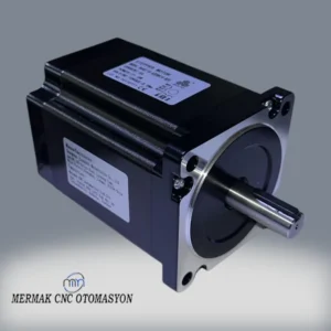
Motion control systems, at the heart of industrial automation, are fundamental to the efficiency and precision of modern manufacturing. Among the most critical components of these systems are undoubtedly stepper motors. Unlike traditional DC or AC motors, stepper motors are electromechanical devices that convert electrical signals into specific, discrete angular steps, providing precise positioning and speed control. This “step-by-step” motion capability makes them indispensable, especially for applications requiring high accuracy.
As industrial automation experts, our field experience shows that stepper motors are much more than simple electric motors; they are intelligent actuators that manage complex machine movements with millimeter precision. Thanks to their open-loop control capabilities, they can often reach a specific position without the need for feedback sensors (like encoders). This feature reduces system costs while simplifying installation and maintenance processes. However, this also means that the motor must be selected correctly, and the mechanical load of the system must be thoroughly analyzed. Stepper motors stand out particularly for their ability to produce high torque at low and medium speeds and their capacity to “hold” their position (holding torque) even when power is cut.
From a technical perspective, the operating principle of a stepper motor involves the sequential switching of magnetic fields in the stator windings, causing the rotor to rotate at a specific angle. Each electrical pulse causes the rotor to move by a fixed angular distance. This angular distance is called the motor’s “step angle” or “step resolution.” For example, a motor with a 1.8-degree step angle requires 200 steps to complete a full revolution (360 degrees). This precision is the main reason they find a wide range of applications, from 3D printers to CNC router machines, medical devices to robotic arms.
This field guide and technical article aim to provide comprehensive information, starting from the basic principles of stepper motors, covering their application areas in industrial automation, technical specifications, selection criteria, and common problems with proposed solutions. Our goal is to serve as a comprehensive resource for engineers, technicians, and automation professionals who wish to enhance both their theoretical knowledge and practical application skills.
What is a Stepper Motor? Applications, Working Principle, and Technical Data
Stepper motors are synchronous brushless DC motors that convert digital electrical pulses into precise mechanical rotational motion. Their fundamental operating principle is based on the magnetic field generated by energizing the coil windings on the stator in a specific sequence, which attracts and repels the magnets or teeth on the rotor. Each energizing step causes the rotor to rotate by a predetermined small angle (step angle). This allows the motor’s position to be controlled very precisely with open-loop control.
Working Principle Details:
- Stator: Typically made of cast iron, consisting of poles with coil windings. These windings are usually two-phase (bipolar or unipolar) or three-phase. The phases are energized in a specific sequence by a controller (stepper motor driver).
- Rotor:
- Permanent Magnet (PM) Stepper Motors: The rotor contains permanent magnets. When the stator phases are energized, the rotor’s magnets align with the stator’s magnetic field. They generally have lower torque and larger step angles (7.5° – 15°).
- Variable Reluctance (VR) Stepper Motors: The rotor has no magnets; instead, it has a toothed iron core. When the stator phases are energized, the rotor positions itself to minimize magnetic reluctance. They can generally achieve higher speeds but lack holding torque.
- Hybrid Stepper Motors: This is the most commonly used type. It combines both permanent magnet and variable reluctance principles. The rotor has axially magnetized toothed poles. This structure provides high torque, small step angles (0.9° – 3.6°), and high precision. Hybrid stepper motors are preferred in the vast majority of industrial automation applications.
- Stepping Modes:
- Full Step: One pair of phases is energized at a time, or two phases are energized simultaneously in opposite directions. Provides the highest torque but has the lowest resolution and most vibration.
- Half Step: Halves the step angle by alternating between full step and single-phase energization. Provides smoother motion and higher resolution.
- Microstepping: Divides the step angle into much smaller increments (e.g., 1/16, 1/32, 1/256 step) by sinusoidally controlling the coil currents. This provides extremely smooth motion, reduced vibration, and very high positioning resolution. Microstepping has become standard in today’s industrial applications.
Applications of Stepper Motors:
Stepper motors play a critical role in many industrial applications requiring precise positioning, speed control, and torque:
- CNC Machines (Computer Numerical Control): Used to control axis movements in milling, turning, laser cutting, and engraving machines. They are indispensable for precise cutting and shaping.
- 3D Printers: Provide high accuracy in additive manufacturing by controlling axial movements (X, Y, Z) and the filament feeding mechanism.
- Robotics Applications: Used for precise motion and positioning in small to medium-sized robotic arms, grippers, and wheel drive systems of mobile robots.
- Packaging Machines: Critical for accurate positioning and feeding of products in operations such as sorting, filling, sealing, and labeling.
- Medical Devices: Preferred in applications requiring precision, such as laboratory analysis equipment, pumps, automated microscopes, and patient positioning systems.
- Textile Machinery: Used for thread feeding, pattern generation, and fabric positioning in sewing machines, embroidery machines, and fabric cutting systems.
- Semiconductor Manufacturing: Used in wafer handling, positioning, and precise optical systems in microchip production.
- Optical and Imaging Systems: Provide precise control in camera focusing and zoom mechanisms, telescopes, microscopes, and pan/tilt units of security cameras.
- Labeling and Dispensing Systems: Used to ensure correct quantities and positions in product labeling, liquid, or powder dispensing systems.
- Automated Assembly Lines: Employed in systems where small parts need to be precisely placed and assembled.
| Parameter | Value/Description |
|---|---|
| Step Angle | Typically 1.8° or 0.9°. The number of steps required for one full revolution (360° / Step Angle). |
| Holding Torque | The maximum torque the motor can apply to maintain its position when energized. Expressed in N.cm or oz-in. |
| Dynamic Torque | The torque the motor can generate while rotating. Generally decreases as speed increases. |
| Number of Phases | Typically 2-phase (bipolar) or 3-phase. 2-phase motors are the most common in industry. |
| Rated Current | The maximum continuous current that should flow through each phase winding. In Amperes (A). |
| Winding Resistance/Inductance | Electrical characteristics of the motor windings. Resistance (Ohms), Inductance (mH). Important for driver selection. |
| Rotor Inertia | The rotor’s resistance to rotational motion. High inertia means slower acceleration/deceleration. |
| Motor Size (NEMA Standard) | Standard sizes like NEMA 11, 14, 17, 23, 34, 42 indicate the motor’s flange size (in inches). |
What is a Stepper Motor? Applications: Key Considerations in the Field
- Correct Motor and Driver Selection: The most critical factor in motor selection is ensuring that the motor’s torque-speed curve matches the application’s required torque and speed profile. For high-inertia loads, higher torque motors or longer acceleration times may be necessary. The motor’s holding torque must be sufficient to hold the load in a static position. Driver selection, on the other hand, should be compatible with the motor’s rated current, ideally having a slightly higher current capacity. Microstepping features are crucial for reducing vibration and increasing resolution. Furthermore, the driver’s supply voltage should be high enough to prevent the motor from losing torque at high speeds (typically 5-20 times the motor’s nominal voltage).
- Mechanical Connection and Alignment: The mechanical connection between the stepper motor and the load directly impacts system performance. When using couplings or gearboxes, flexible and vibration-damping couplings should be preferred. Any axial or angular misalignment at the connection points can place unnecessary stress on the motor bearings, shortening their lifespan and causing vibration. Mechanical elements with backlash should be avoided as much as possible, as they negatively affect positioning accuracy; low-backlash systems (e.g., ball screws) should be used.
- Cabling and Electrical Noise Management: Stepper motor cables can emit electromagnetic interference (EMI) due to the high current pulses carried to the motor phases. This noise can affect control signals or nearby sensitive sensors. Therefore, motor cables should be shielded and routed separately from control signal cables. Cable lengths should be kept as short as possible to prevent voltage drops and signal degradation, and appropriate cable gauges should be used. Grounding is vital for the system’s overall EMI immunity.
- Thermal Management and Operating Environment: Stepper motors are prone to heating, especially under high current or continuous operation. Excessive heat reduces motor performance, damages winding insulation, and shortens its lifespan. The motor’s operating temperature limits (typically 80-100°C) should not be exceeded. If necessary, heatsinks or fans should be used for cooling. Additionally, it is important to select motors with appropriate IP protection classes or ensure the operating environment is free from dust, moisture, vibration, and chemical substances.
- Resonance and Vibration Control: Stepper motors tend to resonate at certain speeds. Resonance can cause excessive motor vibration, noise, and step loss. To prevent this, microstepping, anti-resonance features in the driver, inertia matching (selecting a motor suitable for the load), or speed profiles that quickly pass through resonance regions should be used.
What is a Stepper Motor? Applications: Common Problems and Solutions
Here are some common problems encountered when working with stepper motors in industrial automation and their solutions:
1. Step Loss or Positioning Error:
- Problem: The motor fails to complete all commanded steps, deviating from the target position.
- Causes:
- Motor lacks sufficient torque to move the load (overload).
- Torque drops at high speeds, and the load exceeds the motor’s torque capacity.
- Incorrectly set acceleration/deceleration ramps.
- Operation at resonance points.
- Insufficient driver current settings.
- Mechanical friction or binding.
- Solutions:
- Check the motor’s torque-speed curve to ensure it meets application requirements. If necessary, choose a more powerful motor or increase torque using a gearbox.
- Adjust acceleration and deceleration ramps to be smoother.
- Reduce resonance effects by using microstepping or enable the driver’s anti-resonance feature.
- Set the driver current correctly according to the motor’s rated current.
- Inspect the mechanical system, eliminate friction and binding.
- If necessary, switch to closed-loop stepper motor systems (using encoder feedback).
2. Overheating:
- Problem: The motor’s temperature rises above its normal operating range, becoming too hot to touch.
- Causes:
- Driver current set higher than the motor’s nominal current.
- Continuous operation under high load.
- Insufficient cooling (ambient temperature, lack of airflow).
- Short circuit or damage in motor windings.
- Solutions:
- Set the driver current correctly according to the motor’s datasheet. If available, use the idle current reduction feature.
- Check the motor’s load, ensuring it is not overloaded.
- Add a heatsink to the motor or use active fan cooling.
- Reduce ambient temperature or ensure better ventilation for the motor.
- Measure winding resistances to check for a possible short circuit.
3. High Vibration and Noise:
- Problem: The motor vibrates excessively and produces loud noise during operation.
- Causes:
- Operation in resonance regions.
- Low microstepping resolution (full step or half step).
- Loose mechanical connections or misalignment.
- Unstable motor mounting.
- Incorrect driver settings (e.g., current fluctuations).
- Solutions:
- Increase the microstepping ratio (e.g., 1/8, 1/16, or higher).
- Use the driver’s anti-resonance or dampening features.
- Check the motor and mechanical connections, tighten loose screws, correct misalignment.
- Use high-quality, vibration-damping couplings.
- Check the cabling between the motor and driver, prevent interference that could cause noise.
4. Motor Not Rotating or Rotating in the Wrong Direction:
- Problem: The motor does not respond to motion commands or rotates in the unintended direction.
- Causes:
- Wiring errors (incorrect phase connections, loose connections).
- No power or insufficient power to the driver.
- Control signals (step, direction) not reaching the driver or incorrect polarity.
- Driver malfunction.
- Open circuit in motor windings.
- Solutions:
- Carefully check the wiring between the motor and driver according to the motor’s datasheet. Verify phase sequencing.
- Measure the driver’s power supply and voltage, ensure sufficient power is provided.
- Check control signals (step, direction) with an oscilloscope to confirm correct pulses and polarity.
- Check the driver’s status LEDs, investigate for error codes. Replace the driver if necessary.
- Check the continuity of motor windings with a multimeter.
What is a Stepper Motor? Applications: Conclusion and Expert Advice
Stepper motors are one of the unsung heroes of industrial automation. Thanks to their unique advantages such as precise positioning, repeatability, and cost-effectiveness, they have become an indispensable part of modern production and manufacturing processes. Especially in applications where open-loop control is sufficient and moderate torque and speed are required, stepper motors offer a more economical and simpler solution compared to servo motors. However, this simplicity demands the right engineering approach and system integration.
As an automation expert, my field experience shows that the success of stepper motor systems is directly related not only to the quality of the motor or driver but also to the design of the entire system as a whole. Correct matching of the motor to the load, appropriate driver selection, mechanical design that minimizes vibration and resonance, proper cabling, and thermal management are critical for the system’s long-term, trouble-free operation. A large proportion of problems encountered usually stem from overlooking one of these fundamental principles. For example, step loss is often associated with overload or incorrect speed profiles, while overheating typically results from inadequate current settings or lack of cooling.
In the future, stepper motor technology will continue to evolve, especially with integrated driver motors (where the motor and driver are combined into a single unit) and closed-loop stepper motors (which completely eliminate step loss with encoder feedback). These innovations will expand the application areas of stepper motors and offer more dynamic, reliable solutions. Therefore, it is crucial for industrial automation professionals to master the fundamental principles of stepper motors, be able to provide practical solutions to field problems, and keep up with new technologies. Remembering that each project has its unique dynamics, conducting detailed analysis, and performing tests if necessary to find the most suitable solution are keys to success in the world of automation.
Remember, using the right motor in the right place, in the right way, not only reduces costs but also significantly increases production efficiency and product quality. Stepper motors will continue to be a powerful and reliable tool in achieving these goals. Request a quote on WhatsApp today to learn more about Mermak CNC stepper motor solutions.
FAQ
What is a stepper motor?
A stepper motor is a brushless DC electric motor that divides a full rotation into a number of equal steps. It is controlled by a series of electrical pulses, allowing for precise positioning and speed control without the need for a feedback sensor in open-loop systems. This makes them ideal for applications requiring accurate, repeatable movements.
Where are stepper motors commonly used in industrial applications?
Stepper motors are widely used in industrial automation due to their precision and cost-effectiveness. Common applications include CNC machines (routers, mills, laser cutters), 3D printers, robotics, packaging machinery, medical devices, textile equipment, semiconductor manufacturing, and optical systems for precise positioning and motion control.
What are the different types of stepper motors?
The main types are Permanent Magnet (PM), Variable Reluctance (VR), and Hybrid stepper motors. Hybrid motors are the most common in industrial settings, combining the best features of PM and VR types to offer high torque, small step angles, and high precision. They are typically 2-phase or 3-phase.
What are the key technical specifications to consider when selecting a stepper motor?
Key parameters include step angle (e.g., 1.8° or 0.9°), holding torque (the maximum torque to maintain position when energized), dynamic torque (torque while rotating), number of phases, rated current, winding resistance/inductance, rotor inertia, and NEMA size (e.g., NEMA 23, 34) which defines the motor's flange dimensions. These parameters are crucial for proper motor and driver selection.
What are common problems encountered with stepper motors and how can they be resolved?
Common issues include step loss (motor not reaching target position), overheating, excessive vibration and noise, and the motor not rotating or rotating in the wrong direction. These problems often stem from incorrect motor/driver selection, improper wiring, mechanical misalignment, insufficient cooling, or operating in resonance zones.