
No products in the cart.
Spindle Motor Drive (VFD) Error Codes and Meanings: Field Guide and Technical Article
Contents
- Spindle Motor Drive (VFD) Error Codes and Meanings: Field Guide and Technical Article At the heart of industrial automation, spindle motor drives (VFD – Variable Frequency Drive) play an indispensable role, especially in CNC machines, high-speed machining centers, textile machinery, and similar precision applications. These industrial CNC router drives precisely control the speed, torque, and in some advanced systems, even the position of spindle motors, directly impacting the efficiency and quality of production processes. However, due to their complex structures and high-performance expectations, encountering various fault conditions is inevitable. These faults are typically detected by the drive’s internal protection mechanisms and reported to users as a fault code or alarm. This field guide and technical article focuses on an in-depth analysis of spindle motor drive error codes, their meanings, and practical solutions for industrial automation professionals. Our goal is to provide maintenance and repair teams in the field with quick, accurate, and effective intervention capabilities, thereby minimizing production downtime and increasing system reliability. Introduction and Technical Analysis
- Operating Principle and Technical Data
- Field Considerations
- Common Problems and Solutions
- 1. Overcurrent Fault (OCx)
- 2. Overvoltage Fault (OVx)
- 3. Undervoltage Fault (UVx)
- 4. Overheat Fault (OHx)
- 5. Ground Fault (GFx)
- 6. Encoder/Resolver Fault (EFx)
- 7. External Fault (EXF)
- Expert Advice
- FAQ
Spindle Motor Drive (VFD) Error Codes and Meanings: Field Guide and Technical Article
At the heart of industrial automation, spindle motor drives (VFD – Variable Frequency Drive) play an indispensable role, especially in CNC machines, high-speed machining centers, textile machinery, and similar precision applications. These industrial CNC router drives precisely control the speed, torque, and in some advanced systems, even the position of spindle motors, directly impacting the efficiency and quality of production processes. However, due to their complex structures and high-performance expectations, encountering various fault conditions is inevitable. These faults are typically detected by the drive’s internal protection mechanisms and reported to users as a fault code or alarm. This field guide and technical article focuses on an in-depth analysis of spindle motor drive error codes, their meanings, and practical solutions for industrial automation professionals. Our goal is to provide maintenance and repair teams in the field with quick, accurate, and effective intervention capabilities, thereby minimizing production downtime and increasing system reliability.
Introduction and Technical Analysis
Spindle motor drives are among the most advanced examples of motor control technology. Unlike traditional motor drives, spindle applications typically require high torque precision and dynamic response over a very wide speed range (e.g., from 0 rpm to 24,000 rpm or more). Such drives may have overload capacity, providing short-term torque even above the motor’s rated power, and often utilize advanced vector control algorithms (open-loop or closed-loop – with encoder feedback) to precisely manage the motor’s magnetic flux. These sophisticated control techniques ensure the motor operates at optimal performance across its entire speed range while also increasing energy efficiency.
A fault occurring in a spindle motor drive usually indicates an abnormality in a critical system component or operating condition. These abnormalities can be electrical (overcurrent, overvoltage, ground fault), mechanical (motor jamming, bearing failure), environmental (overtemperature, humidity), or software-related (parameter error, communication issue). The drive’s internal microprocessor continuously monitors input/output currents, voltages, temperatures, and other critical parameters. When a detected abnormality exceeds a predefined threshold or a logic error occurs, the drive stops the system to protect the motor and prevent further damage, displaying the relevant error code to the operator. Correctly interpreting these error codes is vital for quickly identifying the root cause of the malfunction and implementing an effective solution. While each manufacturer (e.g., Siemens, Fanuc, Yaskawa, Delta, ABB, Schneider Electric, etc.) has its own error code system, most error types are based on universal principles.
Operating Principle and Technical Data
A spindle motor drive fundamentally consists of a rectifier that converts AC mains voltage to DC, a DC bus that filters this DC voltage, and an inverter unit that converts this DC voltage into AC voltage of the desired frequency and amplitude, supplying it to the motor. The inverter typically uses PWM (Pulse Width Modulation) technique to control the frequency and amplitude of the voltage applied to the motor windings. This allows for adjustment of the motor’s speed and torque. In advanced spindle drives, encoder or resolver feedback is used to sense the motor’s rotor position or speed. This closed-loop control provides much higher speed and torque precision, better dynamic response, and stable operation even at low speeds. Spindle motors are generally specially designed with low inductance, capable of operating at high frequencies, which requires high-performance PWM output from the drives.
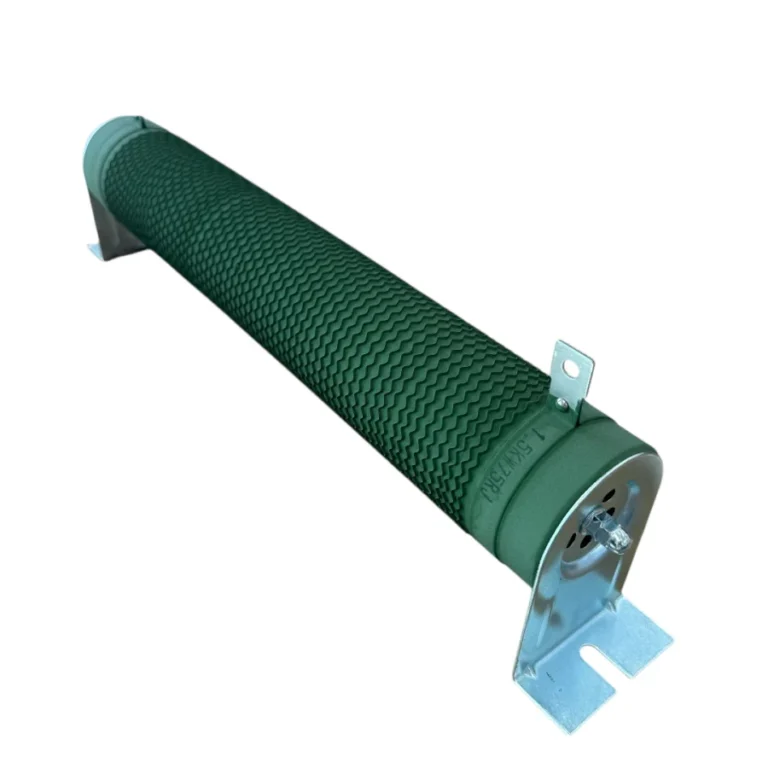
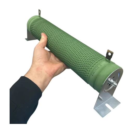
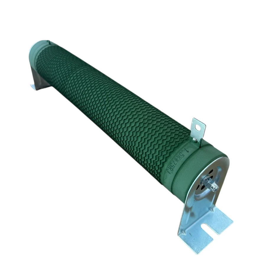
Technically, many parameters influence the performance and fault tolerance of spindle drives. These include carrier frequency, acceleration/deceleration ramps, motor electrical parameters (rated current, voltage, frequency), thermal modeling, and overload capacity. High switching frequencies provide smoother motor current and less motor noise but increase the drive’s heat losses. Acceleration and deceleration ramps directly affect the motor’s dynamic response and mechanical stresses in the system. Correct parameterization of the motor is critical for the effective operation of the drive’s vector control algorithms. Additionally, drives often have an internal dynamic braking unit or an external braking resistor connection point. This resistor dissipates excess energy as heat when the motor operates in regenerative mode (i.e., the motor acts as a generator, feeding energy back to the DC bus), preventing the DC bus voltage from rising. This detailed technical understanding provides engineers and technicians with a comprehensive perspective when interpreting error codes and finding solutions.
| Parameter | Value/Description |
|---|---|
| Output Frequency Range | 0 – 1000 Hz (Typically 400 Hz, over 1000 Hz in some special applications) |
| Control Mode | Vector Control (Sensor/Sensorless), V/f Control, Direct Torque Control (DTC) |
| Overload Capacity | 150% of rated current for 60 seconds (Varies by manufacturer and model) |
| Protection Class | IP20 (Inside panel), IP54 (Protected against dust and splashes) |
| Braking Type | Dynamic Braking (with internal or external resistor), DC Injection Braking |
| Communication Protocol | Modbus RTU, Profibus, Profinet, EtherCAT, CANopen (Depending on application) |
| Operating Temperature Range | -10°C to +50°C (Ambient temperature, derating may be required) |
| Input Voltage | 3 Phase 380-480 VAC (Must be checked against manufacturer datasheet) |
| Efficiency | 95% – 98% (At full load) |

Field Considerations
- Cabling and Grounding Quality: Spindle motor drives can generate significant electromagnetic interference (EMI/RFI) due to high-frequency switching. To control these interferences, motor cables must be shielded, and the shield must be properly grounded at both the drive and motor ends. Additionally, control signal cables should be routed separately from power cables and twisted pair cables should be used to maintain signal integrity. Poor grounding can lead to various ‘ground fault’ or ‘noise’ related errors.
- Environmental Conditions and Cooling: The operating environment of the drive and motor directly affects their lifespan and performance. High ambient temperatures can cause the drive and motor to overheat, leading to thermal protection faults. The temperature inside the control panel should be regularly checked, fans kept clean, and airflow unobstructed. Dust, humidity, and corrosive gases can also damage electronic components. Therefore, selecting drives with appropriate IP ratings and performing regular cleaning is important.
- Parameter Settings and Backup: Each spindle motor and application requires specific parameter settings on the drive. Correct entry of basic motor parameters such as rated current, voltage, frequency, and number of poles is essential for effective vector control. Acceleration/deceleration times, overload limits, and braking parameters must also be appropriate for the application’s dynamics. Incorrect parameters can lead to unstable motor operation, overcurrent, or overvoltage faults. Regularly backing up all parameter settings and managing them with a version control system ensures a quick recovery in case of a drive replacement or reset.
- Motor and Mechanical System Check: Many drive faults actually originate from the motor itself or the mechanical system it is connected to. Situations such as seized motor bearings, shaft misalignment, sudden increase in mechanical load, or insulation failure in motor windings can trigger the drive’s overcurrent or overload protection. Regular motor bearing checks, vibration analysis, and ensuring the mechanical system moves freely play a critical role in preventing drive faults.
- Input Power Quality: The quality of the mains voltage supplied to the drive is important for stable operation. Voltage sags, swells, transient peaks, or phase imbalances can trigger the drive’s undervoltage or overvoltage protection. If necessary, adding a line reactor or an appropriate voltage regulator to the input side can be beneficial.

Common Problems and Solutions
Error codes encountered in spindle motor drives are generally categorized similarly. Here are the most common error codes, their meanings, and suggested solutions:
1. Overcurrent Fault (OCx)
Example Error Codes: OC1, OC2, OC3, F0001 (Siemens), AL01 (Yaskawa), ERR01 (Delta)
Meaning: This fault occurs when the drive’s output current exceeds the set limit. It typically happens during motor acceleration (OC1), deceleration (OC2), or steady-state operation (OC3).
Possible Causes:
- Excessive Mechanical Load: A sudden increase in load due to jamming, bearing failure, or excessive cutting force in the mechanical system connected to the motor (CNC machine, tool).
- Short Circuit: Phase-to-phase or phase-to-ground short circuit in motor windings or motor cables.
- Incorrect Acceleration/Deceleration Times: Setting acceleration or deceleration times too short in the drive parameters can cause the motor current to exceed its nominal value.
- Incorrect Motor Parameters: Incorrect motor rated current, voltage, or other parameters entered into the drive.
- Undersized Drive: The drive’s power is insufficient for the application.
- Motor Fault: Partial short circuit or insulation fault in motor windings.
Solutions:
- Check the mechanical load, identify and repair any jammed or rubbing parts.
- Check motor cables and motor windings for short circuits or ground faults using an insulation (megger) test.
- Increase acceleration/deceleration times.
- Verify the motor parameters entered into the drive and ensure they are correct.
- Ensure an appropriately sized drive is used for the application.
- Test or replace the motor itself.
2. Overvoltage Fault (OVx)
Example Error Codes: OV1, OV2, OV3, F0002 (Siemens), AL02 (Yaskawa), ERR02 (Delta)
Meaning: Occurs when the drive’s DC bus voltage exceeds the set upper limit.
Possible Causes:
- Regenerative Braking: Energy feedback to the DC bus when the motor decelerates rapidly or is driven by an external load (acting like a generator), and this energy is not sufficiently dissipated.
- Braking Resistor Fault/Insufficiency: Disconnected external braking resistor, incorrect resistor value, or insufficient power rating.
- High Input Voltage: Mains voltage significantly higher than the rated value.
- Long Motor Cables: Long motor cables can create a capacitive effect, increasing the DC bus voltage.
Solutions:
- Increase acceleration/deceleration times.
- Check the braking resistor and its connections. If necessary, use a braking resistor with higher power or a different resistance value.
- Check the mains voltage; use a voltage regulator if needed.
- Check the drive’s regenerative braking settings.

3. Undervoltage Fault (UVx)
Example Error Codes: UV1, UV2, F0003 (Siemens), AL03 (Yaskawa), ERR03 (Delta)
Meaning: Occurs when the drive’s DC bus voltage drops below the set lower limit.
Possible Causes:
- Input Power Loss: Interruption of mains voltage to the drive or loss of a phase.
- Low Mains Voltage: Mains voltage significantly lower than the rated value (voltage sag).
- Rectifier Fault: A fault in the drive’s internal rectifier stage.
- Control Circuit Problem: Voltage sensing error in the drive’s internal control board.
Solutions:
- Check the drive’s input power connections and fuses.
- Measure the mains voltage with a multimeter and ensure it is stable.
- Use a line reactor or voltage regulator if necessary.
- Have the drive’s internal hardware checked (by qualified personnel).
4. Overheat Fault (OHx)
Example Error Codes: OH1 (Drive), OH2 (Motor), F0004 (Siemens), AL04 (Yaskawa), ERR04 (Delta)
Meaning: Occurs when the temperature of the drive or motor exceeds the set upper limit.
Possible Causes:
- Drive Overheating: Malfunction of the drive’s cooling fan, clogged cooling fins with dust, excessive ambient temperature, obstructed ventilation openings of the drive.
- Motor Overheating: Motor overload, malfunction of the motor’s cooling fan, clogged motor ventilation holes, disconnected or faulty motor thermistor connection.
Solutions:
- Check, clean, or replace the cooling fans of the drive and motor.
- Check the ambient temperature; improve the cooling system if necessary.
- Ensure the ventilation openings of the drive and motor are clear.
- Check if the motor is overloaded.
- Check the motor’s thermistor connections and sensor.
5. Ground Fault (GFx)
Example Error Codes: GF1, F0005 (Siemens), AL05 (Yaskawa), ERR05 (Delta)
Meaning: A short circuit from any of the drive’s output terminals (U, V, W) to ground.
Possible Causes:
- Motor Cable Fault: Damaged insulation of the motor cable, causing a phase to contact ground.
- Motor Winding Fault: Damaged insulation of motor windings, causing a winding to contact the motor frame (ground).
- Humidity or Dirt: Reduced insulation resistance due to high humidity or conductive dust accumulation.
Solutions:
- Check all cables between the drive and the motor; replace damaged cables.
- Check motor windings for insulation to ground using a megger test.
- Improve environmental conditions; clean humidity and dust accumulations.
6. Encoder/Resolver Fault (EFx)
Example Error Codes: EF1, F0006 (Siemens), AL06 (Yaskawa), ERR06 (Delta)
Meaning: Occurs when the drive cannot correctly receive the encoder or resolver feedback signal from the motor or detects inconsistencies in the signal.
Possible Causes:
- Cable Connection Problem: Broken, loose, or incorrectly connected encoder/resolver cable.
- Encoder/Resolver Fault: Malfunction of the sensor itself.
- Noise: Signal noise due to encoder cables being routed close to power cables or insufficient shielding.
- Incorrect Parameter: Incorrectly set encoder type or resolution parameters in the drive.
Solutions:
- Check the encoder/resolver cable and its connections. Ensure proper shielding.
- Route the cable separately from power cables.
- Test or replace the encoder/resolver.
- Check and ensure the encoder/resolver parameters in the drive are correct.
7. External Fault (EXF)
Example Error Codes: EXF, F0007 (Siemens), AL07 (Yaskawa), ERR07 (Delta)
Meaning: A fault triggered by a signal from a protection device connected to an external input terminal of the drive (e.g., emergency stop button, limit switch, thermal relay).
Possible Causes:
- External Protection Device Triggered: Emergency stop circuit opened, a limit switch activated, motor thermal relay tripped.
- Cable Connection Problem: Break or looseness in the cable going to the external fault input.
Solutions:
- Identify which external device caused the fault and check the relevant device.
- Check the cables going to the external fault input.
- If necessary, check settings for disabling or delaying the external fault input (for temporary tests only).
Expert Advice
Spindle motor drive error codes provide a critical roadmap for diagnosing problems in industrial automation systems. Understanding and correctly interpreting these codes accelerates the troubleshooting process, minimizes production downtime, and reduces maintenance costs. From an expert’s perspective, there is a systematic methodology to follow when approaching error codes: first, document the error code, then consult the relevant drive user manual to understand its detailed meaning, list possible causes, and eliminate each cause to reach the root cause. In this process, it is vital to consider the overall system status (mechanical load, motor temperature, cable connections, environmental conditions, power quality) rather than just focusing on the code on the drive display.
Field experience has shown that many faults stem from basic causes such as simple cable connection issues, incorrect parameter settings, or inadequate cooling. Therefore, regular preventive maintenance programs (fan cleaning, cable checks, parameter backups) and continuous training of operators and maintenance personnel are the most effective strategies for preventing faults and quickly responding to those that occur. Additionally, keeping spare drives and motors for critical applications provides a strategic advantage in minimizing production loss through quick replacement in case of a fault. It must be remembered that since spindle motor drives operate with high voltages and currents, occupational safety rules must be meticulously followed during any intervention, and power disconnection and discharge times must be observed. Do not hesitate to contact the manufacturer’s technical support unit and seek expert assistance for complex problems. This comprehensive guide aims to help professionals in the field confidently approach spindle motor drive error codes and ensure the uninterrupted operation of industrial processes.
FAQ
What are spindle motor drive (VFD) error codes?
Spindle motor drive (VFD) error codes are alphanumeric messages displayed on the drive's panel, indicating a specific fault or abnormal operating condition. These codes help identify the root cause of a problem, such as overcurrent, overvoltage, overheating, or communication issues, allowing for targeted troubleshooting and repair.
What are the most common spindle motor drive error codes?
Common VFD error codes include Overcurrent (OCx), Overvoltage (OVx), Undervoltage (UVx), Overheat (OHx), Ground Fault (GFx), Encoder/Resolver Fault (EFx), and External Fault (EXF). Each category points to a different type of issue within the drive, motor, or connected system.
How do I troubleshoot a spindle motor drive error code?
To troubleshoot a VFD error, first, document the exact error code. Then, consult the drive's user manual for its specific meaning and possible causes. Systematically check for mechanical issues, inspect cabling and connections, verify parameter settings, assess environmental conditions, and test the motor. Always prioritize safety and disconnect power before any physical inspection.
How can I prevent common spindle motor drive faults?
Many VFD errors can be prevented through regular preventive maintenance, such as cleaning cooling fans, checking cable integrity, backing up parameter settings, and ensuring proper grounding. Also, maintaining optimal environmental conditions (temperature, humidity) and correctly sizing the drive for the application are crucial.
Can incorrect parameter settings cause VFD errors?
Yes, incorrect parameter settings are a frequent cause of VFD errors. Parameters like acceleration/deceleration times, motor nominal current/voltage, and encoder resolution must be accurately configured to match the motor and application requirements. Incorrect settings can lead to issues like overcurrent or unstable operation.


