
No products in the cart.
Sigma Profile Dimensions and Weight Calculation Chart: Industrial Automation Field Guide
Contents
Sigma Profile Dimensions and Weight Calculation Chart: A Field Guide and Technical Article for Industrial Automation
Introduction and Technical Analysis
In today’s rapidly evolving world of industrial automation, the fundamental structural elements used in the construction of machines, assembly lines, robotic cells, and various auxiliary structures are critically important for system performance and reliability. In this context, Sigma profiles stand out as indispensable components of modular structural systems. Produced primarily through aluminum extrusion, these profiles are widely used in the industrial automation sector due to their lightweight nature, high strength, easy workability, corrosion resistance, and reusability. Sigma profiles are preferred in numerous applications, from robotic workstations and AGV (Automated Guided Vehicle) chassis to conveyor systems, test and calibration benches, safety barriers, and machine enclosures. The correct selection, precise dimensioning, and accurate weight calculations of these profiles are vital for both the engineering accuracy of the project and for cost and logistics planning. Incorrect profile selection or erroneous weight calculation can lead to structural weaknesses, safety risks, assembly difficulties, and ultimately project failure. This technical article and field guide aim to provide comprehensive information on Sigma profile dimensions, technical specifications, and weight calculation methods for industrial automation professionals.
Operating Principle and Technical Data
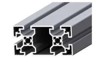
Sigma profiles are typically manufactured from high-strength aluminum alloys (e.g., EN AW-6063 T6) using the extrusion method. This production method gives the profiles a homogeneous structure and high-precision geometric tolerances. The primary reason for calling these profiles “Sigma” is that, despite generally having rectangular or square cross-sections, they feature standardized T-slots on their inner and outer surfaces. These T-slots are the most distinctive feature of the profiles, allowing connection elements (T-nuts, corner connectors, cover profiles, etc.) to be easily inserted, removed, adjusted, and repositioned. This modular structure offers great flexibility to designers and engineers, enabling rapid modifications at every stage, from prototypes to mass production.
Technical data for Sigma profiles is essential for correct selection and design. The main technical parameters include:
- Cross-Sectional Dimensions (Width x Height): The most common profiles have square or rectangular cross-sections such as 20×20 mm, 30×30 mm, 40×40 mm, 45×45 mm, 60×60 mm, 80×80 mm. Additionally, rectangular cross-sections like 40×80 mm, 80×160 mm are available for larger and heavier loads. Each dimension has variants with different wall thicknesses, such as “light series” and “heavy series.” Heavy series offer higher moment of inertia and load-bearing capacity.
- Slot Width (T-slot Width): This is the inner width of the channel where T-nuts and other connection elements are inserted into the profile. It is typically standardized as 6 mm, 8 mm, or 10 mm. This value is critical for the compatibility of the connection elements to be used.
- Center Bore Diameter: Profiles usually have a central bore used for threaded connections (e.g., M8, M10 bolts). This bore is particularly used for connections made from the end face of the profile or for internal cable routing.
- Wall Thickness: This is the thickness of the outer walls and internal support ribs of the profile. Wall thickness directly affects the profile’s weight, moment of inertia, and thus its load-bearing capacity. Heavy series profiles have thicker walls.
- Material Density: For aluminum profiles, the standard density is approximately 2.7 g/cm³ (or 2700 kg/m³). This value is a fundamental constant in weight calculations.
- Cross-Sectional Area (A): This is the area of the profile’s cross-section (in mm²). This value is usually specified in the manufacturer’s technical data sheet and is a key component of weight calculation.
- Weight per Meter (W): This is the weight of one meter length of the profile (in kg/m). This value is also provided by the manufacturer and offers the most practical method for weight calculation. If the weight per meter is unknown, it can be calculated using the following formula:
Weight (kg/m) = Cross-Sectional Area (mm²) * Density (kg/m³) / 1,000,000 (to convert mm² to m²)
Or more simply, if Cross-Sectional Area is in mm² and Density is in g/cm³:
Weight (kg/m) = Cross-Sectional Area (mm²) * Density (g/cm³) * 0.000001 (unit conversion factor)
Example: For a profile with a cross-sectional area of 800 mm² (density 2.7 g/cm³): 800 * 2.7 * 0.000001 = 2.16 kg/m.
- Moment of Inertia (Ix, Iy): This parameter indicates the profile’s resistance to bending (in mm&sup4;). It is given separately for the X and Y axes. A high moment of inertia means the profile will deflect less.
- Section Modulus (Wx, Wy): This parameter indicates the profile’s resistance to bending stresses (in mm³). It is derived from the moment of inertia and used for stress calculations in structural analysis.
These technical data allow engineers to evaluate the suitability of profiles under a specific load, perform deflection calculations, and ensure structural integrity. Especially in industrial automation systems, where dynamic loads, vibrations, and precise positioning requirements are considered, correct profile selection and associated static and dynamic analyses are of great importance.
| Parameter | Value/Description |
|---|---|
| Profile Type Example | 40×40 Light Series Sigma Profile |
| Material | EN AW-6063 T6 Aluminum Alloy |
| Material Density | 2.7 g/cm³ (2700 kg/m³) |
| Cross-Sectional Area (A) | Approx. 500 mm² (Must be checked against manufacturer’s datasheet.) |
| Weight per Meter (kg/m) | Approx. 1.35 kg/m (Varies by cross-sectional area.) |
| Slot Width | 8 mm |
| Center Bore Diameter | Suitable for M8 screw, approx. 6.8 mm |
| Moment of Inertia (Ix, Iy) | Approx. 10.5 cm&sup4; (Must be checked against manufacturer’s datasheet.) |
| Section Modulus (Wx, Wy) | Approx. 5.2 cm³ (Must be checked against manufacturer’s datasheet.) |

Field Considerations
- Cutting Precision and Tolerances: The cut lengths of Sigma profiles are extremely important for ease of assembly and structural integrity. Incorrect cuts can lead to gaps, stresses, or alignment issues during assembly. Precision cutting with CNC-controlled saws should be preferred, and tolerances should be determined according to project requirements.
- Correct Selection and Tightening Torque of Connection Elements: A wide variety of connection elements are available for Sigma profiles (corner connectors, internal connectors, T-nuts, spring nuts, etc.). Each connection element has different load capacities and application areas. Selecting the correct connection element and adhering to the tightening torques specified by the manufacturer ensures the strength of the connections and the stability of the structure. Overtightening can cause profile deformation, while undertightening can lead to loosening.
- Load Distribution and Avoiding Point Loads: In structural designs, it is essential that loads are distributed evenly and balanced across the profiles. Point or excessively concentrated loads can lead to local deformations or fatigue fractures in the profiles. Additional supports, plates, or connection elements with wider bases should be used to distribute loads.
- Thermal Expansion and Contraction: Aluminum expands and contracts due to temperature changes. This should be considered, especially in long structures or environments where large temperature differences are expected. If necessary, expansion gaps should be left, or appropriate connection elements should be used to allow for these movements.
- ESD (Electrostatic Discharge) Protection and Grounding: In industrial automation environments, especially where sensitive electronic equipment is present, ESD protection can be critical. Aluminum profiles are naturally conductive, but electrical continuity can be interrupted at connection points due to anodization or passivation layers. Special ESD connection elements or grounding kits should be used to properly ground the structure and ensure electrical continuity between all profile elements.
- Adaptation to Environmental Conditions: Environmental conditions such as chemical vapors, humidity, dust, or extreme temperatures can affect the lifespan of profiles and connection elements. In aggressive environments, profiles with special coatings or stainless steel connection elements should be preferred. For cleanroom applications, specially designed profiles and accessories with smooth surfaces and minimal particle retention are available.

Common Problems and Solutions
Problem 1: Structural Flexing or Oscillation
Scenario: A conveyor frame on an assembly line or a robotic cell platform exhibits excessive flexing or vibration under the expected load.
Solution:
- Increase Profile Cross-Section: Switching to profiles with larger cross-sections (e.g., 40×80 or 80×80 instead of 40×40) or thicker walls (heavy series) increases the moment of inertia, reducing flexing.
- Add Supports and Cross Bracing: Adding additional vertical, horizontal, or diagonal supports to the structure significantly increases rigidity. Cross bracing is particularly effective for long spans or in areas with dynamic loads.
- Review Connection Elements: Using stronger, more rigid, or larger contact surface connection elements (e.g., reinforced corner connectors or internal connectors instead of standard corner connectors) reduces loosening and flexing at connection points.
- Strengthen Base Connection: Check the integrity of the structure’s connection points to the floor or main machine and reinforce them if necessary.
Problem 2: Loosening of Connection Elements
Scenario: Over time or due to vibrations, profile connections loosen, compromising the stability of the structure.
Solution:
- Apply Correct Tightening Torque: Ensure all connection elements are tightened with a torque wrench according to the manufacturer’s specified torque value.
- Vibration-Resistant Connection Elements: For vibrating environments, use spring washers, serrated lock nuts, or special self-locking T-nuts.
- Chemical Threadlockers: In some cases (especially where disassembly is infrequent), applying a chemical threadlocker (e.g., Loctite) to bolts can be effective.
- Periodic Inspection and Maintenance: Regularly check all connection points and retighten any that have loosened.
Problem 3: Error in Weight Calculation and Logistics/Cost Issues
Scenario: The total structural weight at the end of the project differs significantly from what was expected, increasing shipping costs or exceeding load capacity limits.
Solution:
- Verify with Manufacturer Datasheets: Cross-sectional areas and weights per meter for all profile types and connection elements should be carefully obtained and verified from the respective manufacturer’s technical data sheets. Actual values should be used instead of estimated values.
- Calculate with CAD Software: Modern CAD (Computer-Aided Design) software (SolidWorks, AutoCAD Inventor, CATIA, etc.) can automatically calculate the total weight of all components in the designed structure by inputting material densities. This is the most accurate and reliable method.
- Use a Weight Chart: Create a detailed “weight chart” containing the weight per meter for each profile type and use it as a reference throughout the project.
- Add a Safety Factor: Add a safety factor of 5-10% to the calculated total weight to compensate for potential small errors or added minor components.
Problem 4: Incorrect Profile Selection (Under- or Oversizing)
Scenario: The selected profiles either cannot bear the expected load (undersizing) or are much larger and heavier than necessary (oversizing), leading to waste of cost and space.
Solution:
- Detailed Load Analysis: Analyze all static (fixed) and dynamic (moving, vibrating) loads, instantaneous loads, and wind/earthquake loads (if any) that will act on the structure in detail.
- Static and Strength Calculations: Perform deflection and stress calculations using the selected profile’s moments of inertia, section moduli, and material strength values. Use finite element analysis (FEA) software if necessary.
- Safety Factors: Apply appropriate safety factors in calculations (typically between 1.5 and 3, varying by application) to provide a margin of safety against unexpected load increases or material defects.
- Manufacturer Support and Software: Many Sigma profile manufacturers offer specialized software or engineering support services for profile selection and structural analysis. Utilizing these resources is critical for correct dimensioning.
Expert Advice
Sigma profiles offer indispensable solutions for the modular and flexible structural needs of industrial automation. However, to fully utilize the potential of these profiles and ensure the project is long-lasting, safe, and cost-effective, a meticulous approach to dimensioning and weight calculation processes is required. My experience as a field expert shows that every project has unique requirements, and standard solutions may not always be sufficient. Therefore, performing a detailed engineering analysis during the design phase, carefully reviewing the technical data sheets of all profiles and connection elements to be used, and, if possible, performing virtual prototyping and weight verification with CAD software are of vital importance. Especially in automation projects with dynamic loads, high speeds, or applications requiring precise positioning, moment of inertia and deflection calculations should not be neglected. Furthermore, paying attention to field application details such as precise cutting, correct tightening torque, and electrical continuity during the assembly phase will directly affect the long-term performance of the structure. It should be remembered that a well-designed and correctly assembled Sigma profile structure not only provides cost advantages but also increases machine safety, simplifies maintenance processes, and offers a platform open to future modifications. Therefore, close cooperation with profile suppliers, leveraging their technical expertise, and developing custom solutions when necessary is always the most rational approach. In the complex and dynamic world of industrial automation, attention to detail is the key to project success.
FAQ
What are Sigma profiles and why are they used in industrial automation?
Sigma profiles are modular structural elements, typically made from aluminum alloys using extrusion, featuring T-slots for easy connection. They are widely used in industrial automation for building frames, workstations, and machine enclosures due to their lightweight, high strength, and flexibility.
What technical data should I consider when selecting Sigma profiles?
Key technical data include cross-sectional dimensions (e.g., 40×40 mm), slot width (e.g., 8 mm), wall thickness, material density (approx. 2.7 g/cm³ for aluminum), cross-sectional area, weight per meter, moment of inertia, and section modulus. These parameters are crucial for structural integrity and load-bearing capacity.
How do I accurately calculate the weight of Sigma profiles for my project?
Weight per meter (kg/m) can be found in the manufacturer's datasheet. If not available, calculate it using the formula: Weight (kg/m) = Cross-Sectional Area (mm²) * Density (g/cm³) * 0.000001. For accurate total weight, use CAD software or a detailed weight chart for all components.
My Sigma profile structure is flexing. What are the solutions?
To prevent structural flexing, consider using larger cross-section profiles, heavy series profiles, adding cross bracing or additional supports, and reviewing connection elements for stronger, more rigid options. Ensure base connections are secure.
How can I prevent connection elements from loosening in my Sigma profile assembly?
To prevent loosening, always apply the manufacturer's specified tightening torque with a torque wrench. Use vibration-resistant connection elements like spring washers or self-locking T-nuts. Chemical threadlockers can also be used in low-disassembly areas, and periodic inspections are recommended.



