



































































































































Optimizing Acceleration/Deceleration Ramps (Acc/Dec Time) in Inverter Parameters
📑 Table of contents (Click to open)
Introduction and Technical Analysis
At the heart of industrial automation, inverters (AC drives) play a pivotal role in enhancing the efficiency, precision, and safety of processes by controlling the speed and torque of electric motors. One of the most critical aspects of these control mechanisms is the accurate adjustment of acceleration ramp (Acceleration Time), which is the time it takes for the motor to reach the desired speed from a standstill, and deceleration ramp (Deceleration Time), the time it takes to slow down from the desired speed to a stop or a lower speed. These parameters are collectively known as “Acc/Dec Time,” and their optimization not only extends motor life but also reduces wear on mechanical systems, optimizes energy consumption, and directly impacts process quality. Incorrectly set acceleration/deceleration times can lead to overcurrent or overvoltage faults, mechanical stress and vibrations, and even undesirable shutdowns in production processes and degradation of product quality. This field guide and technical article comprehensively covers the in-depth technical analysis, optimization strategies, and practical field applications of Acc/Dec parameters for industrial automation professionals. Our goal is to explain the engineering principles behind these critical settings and provide readers with the knowledge necessary to make their systems more efficient, safe, and sustainable.
Operating Principle and Technical Data
In inverters, the acceleration and deceleration ramps are essentially based on the principle of gradually increasing or decreasing the motor’s output frequency over a specific time interval. This process is directly related to the motor’s torque and inertia characteristics. Suddenly accelerating a motor to full speed or abruptly stopping it causes high current changes (surges) in the motor windings and shock loads in the mechanical system. The acceleration ramp ensures that the inverter gradually increases the output frequency and, consequently, the motor speed along a specific curve. During this process, the inverter synchronizes the output voltage and frequency to ensure that the motor’s nominal current is not exceeded. Especially in V/f control or vector control modes, the inverter maintains the motor’s magnetic flux, providing the necessary voltage for optimal torque production. The deceleration ramp, on the other hand, ensures the controlled dissipation of the motor’s kinetic energy. During deceleration, the motor can act as a generator, feeding energy back to the grid or the inverter’s DC bus. This can cause the DC bus voltage to rise to dangerous levels, leading to an overvoltage fault in the inverter. Therefore, the deceleration time must be compatible with the system’s capacity to absorb this regenerated energy (e.g., internal braking unit, external braking resistor, or regenerative inverter).
Ramp profiles are typically set as linear, meaning acceleration or deceleration occurs at a constant rate. However, in some applications, especially where sudden torque changes or mechanical shocks are undesirable, S-curve ramps are preferred. S-curve ramps provide smoother transitions at the beginning and end of acceleration and deceleration, minimizing mechanical vibrations and improving process quality. For example, S-curve ramps are ideal for preventing load swinging in crane applications or preventing products from falling in sensitive conveyor systems.
Technical data to consider when determining Acc/Dec times includes:
- Motor Power and Torque Capacity: The motor’s nominal torque determines how quickly it can accelerate or decelerate the load.
- Load’s Moment of Inertia: Loads with high moments of inertia (large fans, flywheels, heavy conveyors) require longer acceleration and deceleration times. Inertia is the resistance to changes in speed.
- Mechanical System Limits: Maximum torque and shock loads that gearboxes, couplings, belts, and other mechanical components can withstand. Sudden speed changes shorten the life of these components.
- Process Requirements: Production line speed, precision, product sensitivity (e.g., preventing spills in liquid transfer), positioning accuracy.
- Energy Efficiency Goals: Very long acceleration times can lead to energy loss, while very short times cause overcurrent. Optimization aims to find this balance.
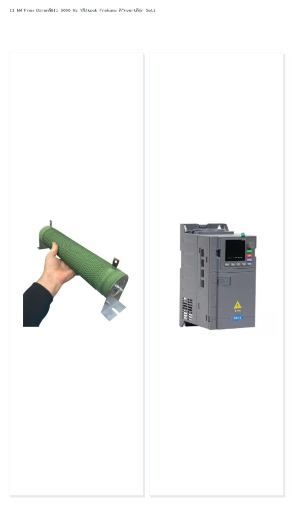
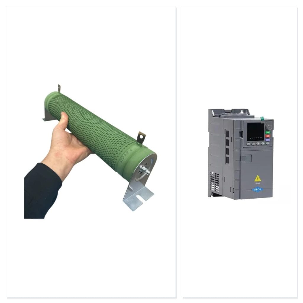
- Braking Capacity: Deceleration time is limited by the inverter’s internal braking capacity, the power of the external braking resistor, and regenerative braking capability. External braking resistors are often required to stop high-inertia loads in a short time.
Proper adjustment of these parameters ensures the inverter and motor operate at optimum performance, maximizes energy efficiency, and extends the general system life. Field engineers should develop a specific optimization strategy for each application using this technical knowledge.
| Parameter | Value/Description |
|---|---|
| Acceleration Time | The time it takes for the motor to reach maximum frequency from 0 Hz. Typically set in seconds. Short times lead to high current, long times to slow response. |
| Deceleration Time | The time it takes for the motor to go from maximum frequency to 0 Hz. Typically set in seconds. Short times lead to overvoltage, long times to slow stopping. |
| Ramp Type | Linear, S-Curve, or custom ramp profiles. Selected according to the mechanical precision of the application. S-curve provides smooth transitions. |
| Overcurrent Limit | The value that limits the inverter’s output current. Reaching this limit during acceleration causes the inverter to fault or slow down acceleration. Must be checked against manufacturer datasheet values. |
| DC Bus Voltage | The voltage level in the inverter’s intermediate DC circuit. During deceleration, the motor’s regenerative energy can increase this voltage, leading to an overvoltage fault. Must be checked against manufacturer datasheet values. |
| Braking Resistor | Converts excess energy generated during deceleration into heat, keeping the DC bus voltage under control. Its power and resistance value are selected according to the load’s inertia and deceleration time. Must be checked against manufacturer datasheet values. |
| Motor Inertia | The resistance of the motor and connected load to rotational motion. High inertia requires longer acceleration/deceleration times or more powerful braking solutions. Must be checked against manufacturer datasheet values. |
Field Considerations
- Mechanical System Analysis: Before adjusting inverter settings, conduct a detailed analysis of the entire mechanical system to which the motor is connected (gearbox, belt pulley, couplings, bearings, gears, shafts). Worn or misaligned components can lead to low efficiency and overloading, affecting Acc/Dec times. Especially with high-inertia loads (large fans, centrifugal pumps, flywheels), the mechanical system’s ability to withstand sudden torque changes is critical. Carefully adjust ramp profiles to avoid mechanical resonance frequencies.
- Motor Thermal Limits and Current Values: Exceeding the motor’s nominal current during acceleration causes overheating of motor windings and shortens insulation life. In addition to the inverter’s overcurrent protection, correctly configure the motor’s thermal model and thermistor feedback. The motor’s cooling capacity should be considered, especially in applications that operate at low speeds for extended periods or frequently accelerate and decelerate. While short acceleration times cause the motor to draw high current initially, this current must be kept within the motor’s thermal limits.
- Power Supply Stability and DC Bus Voltage: Regenerative energy generated by the motor during deceleration can increase the inverter’s DC bus voltage. This leads to an overvoltage fault in the inverter. To manage this risk, a braking resistor of sufficient capacity, an internal braking unit, or a regenerative inverter should be used. Additionally, fluctuations in grid voltage can also affect the DC bus voltage, so grid quality should also be monitored. Very long deceleration times can be a method to keep the DC bus voltage under control, but may not meet process requirements.
- Application-Specific Requirements: Each application has its unique acceleration/deceleration requirements. For example, in crane and lifting systems, soft starts and stops (S-curve) are preferred to prevent load swinging, while cutting or drilling machines may require shorter ramps for fast and precise positioning. In pump applications, deceleration time can be critical to prevent water hammer. Appropriate ramp selection is vital in conveyors to prevent product spillage or damage. In cases of integration into process control loops (PID), the inverter’s ramps must work in harmony with the PID output.
- Coordination with Other Automation Components: The inverter’s Acc/Dec settings must be synchronized with PLC, HMI, SCADA systems, and other sensors/actuators. For example, the stopping of a belt conveyor must be compatible with the processing or feeding mechanism at the next station. In emergency stop scenarios, whether the inverter performs a controlled stop (ramp to stop) or a free stop (coast to stop) should be determined in accordance with safety protocols. This requires communication and integration between safety relays, safety PLCs, and the inverter.
- Environmental Factors and Maintenance: Environmental factors such as high temperature, humidity, dust, or vibration can affect the performance and life of both the motor and the inverter. These factors indirectly play a role in determining Acc/Dec times. For example, since the thermal capacity of a motor operating at high temperatures will decrease, shorter acceleration times may be riskier. Regular maintenance and component inspection help maintain optimum Acc/Dec settings.
Common Problems and Solutions
Incorrectly set Acc/Dec times in inverter parameters can lead to a range of common problems in the field. Recognizing these issues and implementing correct solutions is vital for production continuity and system reliability.
1. Overcurrent Trip During Acceleration:
- Problem: The inverter trips with an “Overcurrent” fault while the motor is accelerating. This typically occurs when the acceleration time is set too short or the load’s inertia is too high, causing the motor to draw current above its nominal value. Mechanical jamming or a faulty motor can also lead to this fault.
- Solution:
- Increase Acceleration Time: This is usually the first and simplest solution. It reduces the current demand by allowing the motor to accelerate the load more slowly.
- Inspect Mechanical System: Check for friction, jamming, bearing failure, or misalignment in the load. A mechanical fault can cause the motor to draw excessive current.
- Verify Motor and Inverter Sizing: Ensure the motor and inverter are correctly sized for the application. An undersized motor or inverter may be insufficient during acceleration.
- Check Torque Limit Settings: Review torque limits (if any) in the inverter. Very low torque limits can hinder acceleration.
- Utilize Vector Control Mode: Advanced vector control algorithms can manage motor torque more efficiently, allowing for shorter acceleration times.
2. Overvoltage Trip During Deceleration:
- Problem: The inverter trips with an “Overvoltage” fault while the motor is decelerating. This happens when the motor generates regenerative energy, causing the inverter’s DC bus voltage to exceed permissible limits. It is typically seen with very short deceleration times or high-inertia loads.
- Solution:
- Increase Deceleration Time: This allows the motor’s kinetic energy to be dissipated over a longer period, reducing the rise in DC bus voltage.
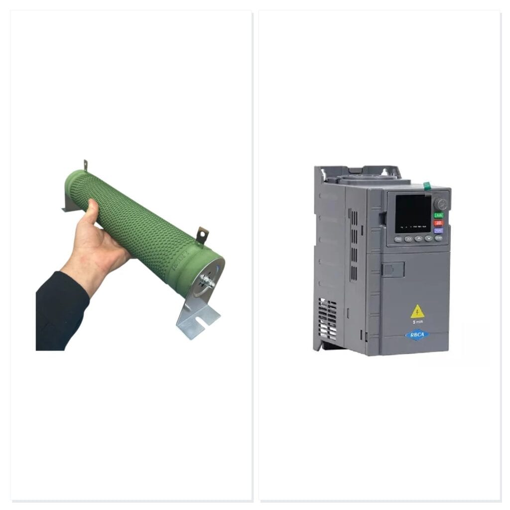
- Add/Size Braking Resistor: Add an external braking resistor of sufficient power or review the size and resistance (Ohm/Watt) of the existing resistor. A braking resistor converts excess energy into heat, limiting the DC bus voltage.
- Use Regenerative Inverter: If the application continuously generates high regenerative energy, consider using regenerative inverters that can feed energy back to the grid.
- “Coast to Stop” Function: In some cases, allowing the motor to coast to a stop (cutting off energy feedback) can be a solution, but this does not provide a controlled stop and may pose safety risks.
- S-curve Deceleration: Smoothing the beginning and end of deceleration can prevent sudden voltage spikes.
3. Mechanical Vibration and Stress:
- Problem: Excessive vibration, noise, or shocks occur in the mechanical system during acceleration or deceleration. This shortens component life and can lead to failures. Harsh starts and stops are common causes.
- Solution:
- Use S-curve Ramps: Provides smooth transitions at the beginning and end of acceleration and deceleration, significantly reducing mechanical shocks and vibrations.
- Optimize Ramp Times: Very short times cause mechanical shock, while very long times can increase the risk of remaining at resonance frequencies. Find the optimum point through trial and error and observation.
- Mechanical Inspection: Check the condition and alignment of couplings, bearings, gears, and other connecting elements. Loose or worn parts can increase vibration.
- Avoid Resonance Frequencies: Some inverters have a skip frequency feature for specific frequency ranges. Identify your system’s natural resonance frequencies and skip these ranges to reduce vibration.
4. Degradation of Process Quality (e.g., Product Spillage, Positioning Error):
- Problem: In applications requiring liquid transfer, precise lifting, or positioning, incorrect Acc/Dec settings lead to product spillage, displacement, damage, or errors in precise positioning.
- Solution:
- Fine-Tune Ramp Profile: Precisely adjust Acc/Dec times and ramp type (linear, S-curve) according to the application’s specific needs. Use multi-step ramps or custom ramp profiles if necessary.
- Feedback Control (PID): If the process requires precision, control the inverter speed with a PID control loop. This provides more dynamic and precise control during acceleration and deceleration.
- Start and End Frequency Settings: In some applications, the motor may need to accelerate from a specific start frequency rather than zero, or stop at a particular frequency. Ensure these settings are correctly configured.
5. Slow Response Time or Insufficient Performance:
- Problem: The motor is too slow to reach the desired speed or stop, which reduces production capacity or disrupts process timing.
- Solution:
- Shorten Acc/Dec Times (Carefully): Try to find the shortest possible times without causing the overcurrent/overvoltage and mechanical stress problems mentioned above.
- Evaluate Motor and Inverter Power: Check if the current system provides enough torque to move the load at the desired speed and time. A more powerful motor or inverter may be required if necessary.
- Improve Braking Solutions: If deceleration time is insufficient, increase deceleration capacity with a more powerful braking resistor or regenerative braking solutions.
In each problem scenario, understanding the underlying mechanical, electrical, or process-related causes and adopting a holistic approach, rather than just changing inverter parameters, will provide lasting and effective solutions.
Expert Advice
Optimizing acceleration/deceleration ramps in inverter parameters has a direct and significant impact on the performance, reliability, and lifespan of industrial automation systems. As discussed in this article, correctly setting Acc/Dec times is more than just an inverter adjustment; it is a critical engineering decision that affects a wide range of factors, from motor thermal health to mechanical component wear, energy efficiency, and process quality. Based on our field experience, adopting a holistic perspective when approaching this optimization process is essential. Not only electrical, but also mechanical and process engineering disciplines must be considered. Acceleration and deceleration times require careful analysis of numerous factors such as load inertia, motor torque capacity, mechanical system durability, and process sensitivity. Remember that a “one size fits all” approach is not applicable here; each application has its unique dynamics and requires customized solutions tailored to these dynamics.
As expert advice, we recommend approaching the optimization process with an iterative approach. Start with general values derived from manufacturer recommendations or similar applications, then fine-tune by testing and observing the system step-by-step. Especially in critical applications, monitoring parameters such as motor current, voltage, torque, and vibration using data acquisition and analysis systems (SCADA, HMI) will provide invaluable information for finding optimal settings. When encountering overcurrent or overvoltage faults, instead of immediately extending the ramps, first check for any jamming or wear in the mechanical system. When deceleration times need to be shortened, ensure that the braking resistor or regenerative capacity is sufficient. Also, do not overlook the advantages offered by S-curve ramps; they can make a significant difference in reducing mechanical stress and improving process quality in sensitive and dynamic applications. Finally, meticulously documenting all adjustments and test results will create a valuable resource for future troubleshooting and system improvements. Through continuous learning and experimentation, you can fully unlock the potential of your industrial automation systems, maximizing efficiency and reliability.
FAQ
What is Acc/Dec Time in inverter parameters?
Acc/Dec Time refers to the acceleration and deceleration ramp times in an inverter. Acceleration time is how long it takes for the motor to reach its target speed, while deceleration time is how long it takes to slow down or stop. Proper optimization prevents issues like overcurrent, overvoltage, and mechanical stress.
What are the common problems caused by improper Acc/Dec settings?
Incorrect Acc/Dec settings can lead to overcurrent trips during acceleration, overvoltage trips during deceleration, excessive mechanical vibration and stress, and degradation of process quality (e.g., product spillage, positioning errors).
How can I troubleshoot overcurrent and overvoltage faults related to Acc/Dec parameters?
To prevent overcurrent, increase the acceleration time, check the mechanical system for issues, verify motor and inverter sizing, and consider using vector control. For overvoltage, increase deceleration time, add or correctly size a braking resistor, or consider a regenerative inverter.
When should I use S-curve ramps instead of linear ramps?
S-curve ramps provide smoother transitions at the beginning and end of acceleration and deceleration. They are ideal for applications where sudden torque changes or mechanical shocks are undesirable, such as crane systems or sensitive conveyor belts, as they minimize vibrations and improve process quality.
What technical data should be considered when setting Acc/Dec times?
Key factors include motor power and torque capacity, the load's moment of inertia, mechanical system limits, specific process requirements (e.g., precision, product sensitivity), energy efficiency goals, and the inverter's braking capacity.


