
No products in the cart.
Mini CNC Machine Settings for PCB Engraving and Drilling: A Technical Guide

Contents
Mini CNC Machine Settings for PCB Engraving and Drilling: A Technical Guide
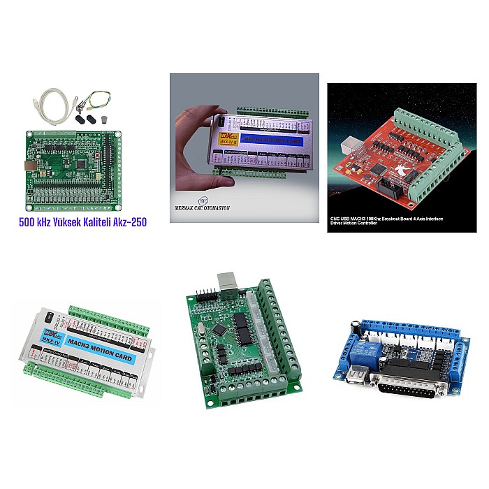
Introduction and Technical Analysis
The industrial automation sector constantly seeks innovative and cost-effective solutions for rapid prototyping, accelerating R&D processes, and meeting small-scale specialized production needs. In this context, Mini CNC (Computer Numerical Control) machines have become an indispensable tool for PCB (Printed Circuit Board) engraving and drilling applications. Offering a cleaner, faster, and more environmentally friendly alternative to traditional chemical etching methods, these systems significantly streamline the process for engineers and technicians to transform their designs into physical products. However, to fully leverage the potential of these systems, the importance of correct settings, appropriate tool selection, and precise calibration is critical. This technical article comprehensively covers all details of Mini CNC PCB engraving and drilling processes, optimal setting parameters, field experiences, and solutions for common problems encountered by industrial automation professionals. Our objective is to maximize the advantages provided by this technology, thereby increasing production efficiency and product quality. Precise trace widths, accurate hole positioning, and surface quality are directly related to the correct configuration of Mini CNC machines, especially given the complexity of modern electronic circuits. This guide aims to help all users, from beginners to advanced, master Mini CNC PCB production by providing the necessary technical knowledge.
Operating Principle and Technical Data
Mini CNC machines utilize the principle of subtractive manufacturing to perform PCB engraving and drilling operations. This process relies on the mechanical removal of unwanted copper from a copper-clad laminate (typically FR-4). The workflow usually begins with designing the PCB in a CAD (Computer-Aided Design) software (e.g., Eagle, KiCad, Altium Designer). Subsequently, this design must be converted into command sequences called G-code, which the machine can understand, via CAM (Computer-Aided Manufacturing) software (e.g., FlatCAM, bCNC, UGS). G-code specifies the coordinates, speed, spindle (spindle motor) RPM, and depth of the tool’s movement. The machine interprets this G-code to precisely control the stepper motors on the X, Y, and Z axes. The X and Y axes provide horizontal tool movement, while the Z axis adjusts the engraving or drilling depth. The spindle motor ensures that the high-speed rotating cutting tool (V-bit, drill bit) processes the material.
From an engineering perspective, the performance of a Mini CNC depends on several technical parameters. Spindle speed (RPM) determines how fast the tool rotates and directly affects surface quality, tool life, and material removal rate. High spindle speeds (10,000 – 30,000 RPM) are generally preferred for PCB engraving, while lower speeds or peck drilling methods may be applied for drilling operations. Feed rate indicates how fast the tool moves across the material (mm/min). This parameter must be optimized in conjunction with the engraving depth and tool type. Excessive feed rates can lead to tool breakage, while very low feed rates can degrade surface quality and cause the tool to overheat. Depth of Cut is critical, especially when working with V-bits. Precise depths, typically between 0.05 mm and 0.2 mm, are used to create copper traces. Drilling depth is determined by the PCB thickness and hole type (through-hole, blind-hole). The machine’s mechanical resolution and repeatability are directly related to the step accuracy of the stepper motors, the quality of the lead screw, and the precision of the linear guide rails. In industrial applications, repeatability values better than +/- 0.02 mm are sought. Furthermore, the tool diameters used (V-bits and drill bits ranging from 0.1 mm to 3.0 mm) and the type of PCB material (FR-4, aluminum-based PCBs) also play a significant role in determining the settings.
| Parameter | Value/Description |
|---|---|
| Spindle Speed (Engraving) | 18,000 – 24,000 RPM (V-bit, 0.1-0.2mm tip) |
| Spindle Speed (Drilling) | 10,000 – 15,000 RPM (0.5-2.0mm drill bit) |
| Feed Rate (Engraving) | 250 – 500 mm/min (Adjusted according to copper thickness and tool angle) |
| Feed Rate (Drilling) | 100 – 200 mm/min (According to tool diameter and material hardness) |
| Engraving Depth (Per Pass) | 0.05 – 0.15 mm (Single pass depth, precise adjustment with Z-probe) |
| Drilling Depth | PCB thickness + 0.2 mm (Retract distance added if necessary) |
| Tool Type (Engraving) | V-Bit (0.1mm tip, 10-30 degree angle) |
| Tool Type (Drilling) | Carbide Drill Bit (0.3mm – 3.0mm diameter range) |
| PCB Material | FR-4 (1.6mm thickness common use) |
| Minimum Trace Width | 0.15 mm (Depends on tool tip and precision) |
| Repeatability | ± 0.02 mm (For high-precision machines) |
| Z-Probe Calibration Accuracy | ± 0.01 mm |
Field Considerations
- Tool Selection and Calibration: Selecting the appropriate tool for the trace width, pad sizes, and hole diameters of the PCB to be processed is critically important. For engraving, V-bits with a 10 to 30-degree angle and a 0.1 mm tip diameter are generally preferred, while carbide drill bits are used for drilling. Z-axis calibration during tool changes, especially automatic calibration with a Z-probe, plays a vital role in maintaining consistent engraving depth. The zero point should be determined with the Z-probe after each tool change or at the start of a job. Ensure the tool is correctly inserted and tightened in the collet.
- Material Fixturing and Flatness: Securing the PCB to the work table in an absolutely flat and stable manner directly affects engraving quality. Vacuum table systems offer the most ideal solutions, while double-sided tape or mechanical clamping fixtures can be used for smaller Mini CNC machines. Warping or vibrations on the material surface lead to inconsistencies in engraving depth and broken traces. Periodically checking and, if necessary, surfacing the table is important.
- Parameter Optimization and Test Cuts: Parameters such as spindle speed, feed rate, and engraving depth mentioned above require fine-tuning based on the thickness of the PCB material used, the characteristics of the copper layer, and the wear condition of the tool. Performing small, non-critical test engravings and drills for each new material or tool type to find optimal settings prevents waste of time and material. Carbide tools, instead of High-Speed Steel (HSS) tools, offer longer life and more precise machining capabilities.
- Environmental Conditions and Dust Management: Glass fiber and copper dust generated during PCB processing pose risks to both the machine’s lifespan and the operator’s health. The use of an effective dust extraction system is mandatory. Furthermore, stable environmental conditions such as temperature and humidity positively impact the performance of the machine’s mechanical and electronic components. Protective measures should be taken to prevent dust from reaching electronic components and moving parts.
- Software and G-Code Verification: Checking the G-code generated by the CAM software with a simulation program before starting machining prevents potential errors (collisions, incorrect tool paths, erroneous depths). Manually inspecting the G-code and verifying the accuracy of Z-axis movements, in particular, can prevent unexpected malfunctions. Ensure that parameters such as tool offset and workpiece zero are correctly entered in the software settings.
- Maintenance and Cleaning: Regular maintenance of Mini CNC machines is essential for long-lasting and error-free operation. Periodically cleaning and lubricating moving axes (lead screw, linear guide rail) prevents backlash. Air filters of the spindle motor should be cleaned, and the condition of its bearings checked. Tool sharpness should be regularly inspected, and worn tools replaced in a timely manner. The integrity of electrical connections and cables should also be reviewed for safety and performance.
Common Problems and Solutions
Some common problems encountered during Mini CNC PCB processing and practical solutions are detailed below:
- Inconsistent Trace Width or Insufficient Engraving:
- Problem: Engraved traces are out of standard width, or copper is not completely removed in some areas.
- Possible Causes: Z-axis calibration error, uneven table surface, worn or broken tool, incorrect engraving depth setting, poorly secured PCB.
- Solution: Recalibrate the Z-axis zero point with a Z-probe. Check the flatness of the table surface; perform surfacing if necessary. Inspect the tool and replace it if worn. Optimize the engraving depth between 0.05-0.15 mm, according to copper thickness. Secure the PCB more firmly.
- Tool Breakage or Excessive Wear:
- Problem: The tool frequently breaks or wears out much faster than expected during engraving or drilling.
- Possible Causes: Excessive feed rate, insufficient spindle speed, incorrect tool selection (not suitable for material hardness), tool incorrectly or loosely inserted into the holder, excessive pressure on the material.
- Solution: Reduce the feed rate. Increase the spindle speed (especially for small diameter tools). Use a carbide tool appropriate for the material. Insert the tool correctly and tightly into the holder. Reduce the engraving depth to lighten the load on the tool.
- Incorrect Hole Placement or Deviation:
- Problem: Holes deviate from planned positions or are not circular.
- Possible Causes: Mechanical backlash or looseness, stepper motors losing steps, reference point (origin) error, incorrect coordinate settings in CAM software.
- Solution: Check and eliminate backlash in the machine’s mechanical components. Adjust belt tension in belted systems, and nut play in lead screw systems. Check the current settings of the stepper motors. Before starting machining, correctly define and fix the reference point. Carefully review the coordinate system and G-code output in the CAM software.
- Poor Surface Quality (Burrs, Rough Surface):
- Problem: Engraved surfaces are rough, burred, or contain unwanted copper residues.
- Possible Causes: Excessive spindle speed, insufficient feed rate, dull or worn tool, vibration on the material, incorrect tool angle.
- Solution: Optimize spindle speed and feed rate; generally, slower feed rates and higher spindle speeds provide better surface quality. Replace the tool with a sharp new one. Check the stability of the PCB and the overall vibration of the machine. Ensure the V-bit angle is appropriate for the copper thickness (narrower angles can provide cleaner edges).
- Machine Vibration and Abnormal Noise:
- Problem: Excessive vibration or unusual noises emanate from the machine during machining.
- Possible Causes: Loose mechanical connections, unbalanced spindle motor, worn bearings, incorrect assembly, unstable work table.
- Solution: Check and tighten all bolt and nut connections. Check the balance of the spindle motor; if there is excessive vibration, consider replacing the bearings or the motor. Ensure the machine is seated on a flat and stable surface. Periodically check and lubricate bearings during maintenance.
Expert Advice
Mini CNC machines have provided invaluable flexibility and speed to the industrial automation sector for PCB prototyping and small-scale production. The settings, principles, and troubleshooting methods covered in this detailed field guide and technical article offer a fundamental roadmap for achieving maximum efficiency from this technology. It should be remembered that every Mini CNC machine and every PCB project has its unique dynamics. Therefore, the parameters presented here are a starting point and will require continuous experimentation, observation, and optimization in real-world applications. The most important advice for field engineers and technicians is to meticulously document processes, record the results of each setting change, and use this data as a reference for future projects. I would like to emphasize once again that tool selection, material fixturing precision, and Z-axis calibration are the most critical factors directly affecting PCB engraving and drilling quality. Furthermore, adhering to occupational safety rules, especially ensuring the effectiveness of dust extraction systems and using protective equipment, is indispensable for a long-term and healthy working environment. With the automation and digitalization trends brought by Industry 4.0, Mini CNC technologies will further develop, offering more integrated and intelligent solutions. Expertise in this field is of great importance for adapting to future innovations and gaining a competitive advantage. Continuous learning and gaining experience are the keys to achieving excellence in this domain.
FAQ
How do Mini CNC machines work for PCB engraving and drilling?
Mini CNC machines engrave and drill PCBs by mechanically removing unwanted copper from a copper-clad laminate using a high-speed rotating tool. The process is guided by G-code generated from CAD/CAM software, controlling the precise movements of stepper motors on the X, Y, and Z axes.
What are the optimal settings for Mini CNC PCB engraving and drilling?
Key parameters include spindle speed (18,000-24,000 RPM for engraving, 10,000-15,000 RPM for drilling), feed rate (250-500 mm/min for engraving, 100-200 mm/min for drilling), and engraving depth (0.05-0.15 mm per pass). Tool type (V-bits for engraving, carbide drill bits for drilling) and PCB material (FR-4) are also critical.
What are common problems encountered during Mini CNC PCB processing and how can they be resolved?
Common issues include inconsistent trace width, tool breakage, incorrect hole placement, and poor surface quality. Solutions involve recalibrating the Z-axis, ensuring material flatness, optimizing feed and spindle speeds, using appropriate tools, and checking for mechanical backlash.
What are the most critical factors for achieving high-quality PCB engraving and drilling?
Proper tool selection (V-bits for engraving, carbide drill bits for drilling), precise Z-axis calibration using a Z-probe, and secure, flat material fixturing are critical for achieving high-quality PCB results. Test cuts are recommended for new materials or tools.
Why is dust management and environmental control important for Mini CNC PCB operations?
Effective dust extraction systems are mandatory to manage glass fiber and copper dust, protecting both the machine and operator health. Stable environmental conditions (temperature, humidity) also contribute to optimal machine performance and longevity.



