No products in the cart.
Mach3 Setup, Configuration, and Axis Calibration (Complete Guide)

Contents
- Introduction and Technical Analysis As a cornerstone of industrial automation, CNC (Computer Numerical Control) machines hold an indispensable position in modern manufacturing processes. The control software, acting as the brain of these machines, is critically important for precision, repeatability, and efficiency. Mach3 is a popular and cost-effective CNC control software, especially for small to medium-sized workshops, prototyping laboratories, and educational institutions. This Microsoft Windows-based software controls stepper or servo motors via a parallel port or external motion controllers, converting G-code commands into physical axis movements. This guide provides a comprehensive roadmap for experts in the industrial automation sector for the successful installation of Mach3 software, configuration of its basic settings, and meticulous axis calibration. Correct installation and calibration ensure the machine operates with expected precision, prevents material waste, improves production quality, and ensures operator safety. This detailed approach aims to offer practical solutions to technical challenges encountered in both new installations and the optimization of existing systems. Operating Principle and Technical Data
- Field Considerations for Industrial CNC Router Machines
- Common Issues and Solutions for Industrial CNC Router Machines
- Expert Advice for Industrial CNC Router Machine Operators
- FAQ
Introduction and Technical Analysis
As a cornerstone of industrial automation, CNC (Computer Numerical Control) machines hold an indispensable position in modern manufacturing processes. The control software, acting as the brain of these machines, is critically important for precision, repeatability, and efficiency. Mach3 is a popular and cost-effective CNC control software, especially for small to medium-sized workshops, prototyping laboratories, and educational institutions. This Microsoft Windows-based software controls stepper or servo motors via a parallel port or external motion controllers, converting G-code commands into physical axis movements. This guide provides a comprehensive roadmap for experts in the industrial automation sector for the successful installation of Mach3 software, configuration of its basic settings, and meticulous axis calibration. Correct installation and calibration ensure the machine operates with expected precision, prevents material waste, improves production quality, and ensures operator safety. This detailed approach aims to offer practical solutions to technical challenges encountered in both new installations and the optimization of existing systems.
Operating Principle and Technical Data
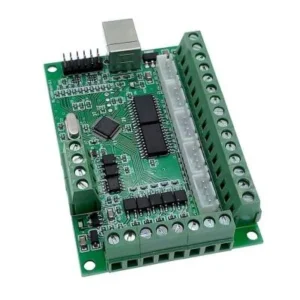
Mach3 operates by sending step and direction signals to the CNC machine’s drivers via a computer’s parallel port or a dedicated external motion controller. It interprets standardized toolpath commands known as G-code and converts these commands into electrical pulse sequences that cause the axis motors to move at a specific speed and direction. When these pulses reach the stepper motor drivers, the drivers apply the appropriate current to the motor windings, causing the motor to rotate at a specified angle. In servo systems, Mach3 typically sends commands to an external servo drive, and the drive provides closed-loop control by feeding back the motor’s position via an encoder. The Mach3 kernel speed determines the maximum number of pulses that can be generated per second, directly affecting the highest speed and precision the machine can achieve. In industrial applications, due to the limitations of the parallel port, Ethernet or USB-based external motion controllers are often preferred. These controllers offer higher pulse frequencies, more stable communication, and better compatibility with modern operating systems. The installation process begins with installing the Mach3 software on a Windows operating system (typically 32-bit Windows XP or Windows 7 for parallel port use). Subsequently, in the Port and Pins section, the step and direction pins for each axis, limit switches, emergency stop (E-stop) button, home switches, and spindle control pins are defined according to the machine’s physical connections. At this stage, the active high or active low structures of the input and output signals must be correctly set. The Motor Tuning section is a critical step where steps per unit, maximum velocity, and acceleration values are entered for each axis. The steps per unit value is calculated by combining the number of steps required for one full motor revolution, the driver’s micro-stepping setting, and the mechanical system (lead screw pitch or belt ratio). Correctly setting this value ensures that axis movements correspond precisely to the actual distance. Velocity and acceleration values determine the maximum dynamic performance that the motors and mechanical system can handle. Incorrectly set acceleration values can lead to motor stalling or mechanical stress. Axis calibration is the process of physically verifying the accuracy of these calculated steps per unit values and is a fundamental step for machine precision. For spindle control, RPM adjustment and on/off functions are typically configured using PWM (Pulse Width Modulation) signals or relays. The correct integration of these systems is essential for precise machining capability.
| Parameter | Value/Description |
|---|---|
| Mach3 Kernel Speed (Frequency) | 25 kHz, 35 kHz, 45 kHz (typical for parallel port). Between 100 kHz – 1 MHz for external controllers. |
| Axis Steps per Unit | (Motor Steps/Revolution * Microstepping Ratio) / (Lead Screw Pitch or Belt Ratio). Example: 200 * 8 / 5mm = 320 steps/mm. |
| Maximum Velocity | Adjusted according to the mechanical and motor capacity of each axis. Example: 3000 mm/min for X-axis. |
| Acceleration | Adjusted considering the inertia of motors and the mechanical system. Example: 500 mm/s² for X-axis. |
| Microstepping Ratio | Depends on the driver setting. Ratios like 1/2, 1/4, 1/8, 1/16. Typically 1/8 or 1/16 is preferred. |
| Parallel Port Base Address | Typically 0x378 or 0x278. Should be checked from the computer’s BIOS or Device Manager. |
| Limit/Home Switch Type | Normally Open (NO) or Normally Closed (NC). NC is safer in industrial environments. |
| Input Signal Debounce Interval | To prevent false triggers caused by noise. Typically between 100-500 ms. Should be checked according to the manufacturer’s datasheet value. |

Field Considerations for Industrial CNC Router Machines
- Electrical Noise and Grounding: In industrial environments, high-current motors, inverters, and other electronic devices can generate significant electrical noise (EMI/RFI). This noise can corrupt Mach3’s control signals, leading to axis misalignments, false limit switch triggers, or unexpected machine behavior. It is crucial that all control cables (especially step/dir signal cables) are shielded and that these shields are properly grounded at only one point (typically on the control panel side). Furthermore, ensure that the entire system is connected to a robust general grounding line. Distances between power supplies and drivers should be minimized, and power cables should be routed separately from signal cables.
- Hardware Compatibility and Stability: For Mach3’s parallel port usage, a 32-bit Windows XP or Windows 7 operating system is generally recommended. Modern 64-bit operating systems or Windows 8/10 may not provide stable operation with parallel port drivers. In such cases, using Ethernet or USB-based external motion controllers (e.g., SmoothStepper, UC100, xPro V5) offers a safer and more stable solution. These controllers perform pulse generation independently of the computer’s operating system, providing higher and more stable pulse frequencies. It is important that the computer meets minimum system requirements, unnecessary background programs are disabled, and power-saving settings are configured for performance.
- Mechanical Precision and Backlash: No matter how well Mach3’s software calibration is performed, mechanical backlash or flex in the machine’s structure directly affects machining precision. Gaps in lead screws, nuts, couplings, and bearings, in particular, cause the tool to fail to reach the desired position precisely during direction changes. This leads to significant dimensional errors and surface quality issues, especially in precision operations like milling and drilling. Mechanically minimizing backlash (e.g., anti-backlash nuts, preloaded lead screws) is the first step. For unavoidable backlash, Mach3’s Backlash Compensation feature can be used, but this software solution does not completely eliminate mechanical play; it only reduces its effects to some extent and can sometimes lead to dynamic performance issues.
- Safety Protocols and Emergency Management: Safety is always the highest priority in industrial automation systems. In Mach3 setup, it is mandatory to correctly configure and test the Emergency Stop (E-stop) button and all axis limit switches. Limit switches prevent the machine from exceeding its mechanical boundaries, protecting both the machine and the operator. These switches are typically connected with NC (Normally Closed) contacts, which provides the advantage of putting the system into a safe mode even in cases of cable breakage. Additionally, a detailed Safe Operating Procedure (SOP) should be created for each machine, and all operators should be trained on these procedures. Performing toolpath simulations before starting machining and using appropriate clamping methods according to the workpiece are also important.
- Profile Backup and Version Control: After Mach3 installation and configuration are complete, regularly backing up the created Mach3 profile (XML file) is critically important. This ensures that the machine can be quickly restored to its previous working state in case of system failure, operating system crash, or accidental setting changes. If multiple Mach3 profiles are used for different machines or different machining tasks, clearly labeling each profile and performing version control will prevent confusion and errors. G-code files and tool libraries should also be backed up regularly.
- Cooling and Environmental Conditions: Stepper or servo motor drivers generate significant heat during operation. Keeping the temperature within the control panel within certain limits is important to extend the life and ensure stable operation of drivers and other electronic components. Adequate ventilation or active cooling (fans) should be provided within the control panel. Furthermore, environmental conditions such as dust, humidity, vibration, and temperature in the machine’s operating environment also affect the performance and lifespan of electronic components. In aggressive environments, enclosures and components with high IP protection ratings should be preferred.

Common Issues and Solutions for Industrial CNC Router Machines
Problems encountered in Mach3-based CNC systems are typically electrical, mechanical, or software-related. A systematic approach is necessary for accurate diagnosis and resolution of these issues.
- Axis Skipping or Drifting (Lost Steps): This problem manifests as the motor failing to reach the desired position, resulting in dimensional errors on the workpiece.
- Solution: First, check the Motor Tuning settings. Maximum velocity and acceleration values might exceed the motor’s capacity; gradually reduce these values. Check the current settings of the motor drivers and ensure they match the motor’s nominal current. Check for mechanical binding, excessive friction, or backlash. Electrical noise can also cause this; review shielded cabling and proper grounding. Check motor cooling; overheating motors can lose performance.
- Incorrect Axis Movement or Reverse Direction: An axis does not move when commanded or moves in the opposite direction.
- Solution: Check the Step and Dir pin settings in Mach3’s Port and Pins -> Motor Outputs section. Ensure pin numbers are correct and match the driver connections. If the axis moves in reverse, change the checkmark for the corresponding axis’s “Dir Low Active” box (uncheck if checked, check if unchecked). Check the connection of the direction pin on the driver.
- Limit Switch Errors or Continuous Triggering: The machine does not move, or the limit switch warning appears continuously active.
- Solution: Ensure the limit switch pins and “Active Low” settings in Port and Pins -> Input Signals section are correct. Check if the switches are NC (Normally Closed) or NO (Normally Open) and adjust the setting accordingly. Test for short circuits or breaks in switch cables with a multimeter. For false triggers caused by electrical noise, increase the Debounce Interval value in Config -> General Config section (e.g., 100-500ms).
- Mach3 Freezing, Crashing, or Delays: The software becomes unresponsive, slows down, or crashes completely at intervals.
- Solution: Ensure the computer has an appropriate operating system for Mach3 (32-bit Windows XP/7). Close unnecessary background programs. Set the parallel port mode to EPP or ECP in the computer’s BIOS settings. Try lowering the Kernel Speed setting in Mach3’s Config -> Ports and Pins -> Motor Outputs section. Check for issues with the computer’s hardware (RAM, CPU) or Windows drivers. If an external motion controller is used, ensure its drivers are up-to-date and correctly installed.
- Calibration Inconsistency and Dimensional Errors: The machine travels a different distance than commanded.
- Solution: Ensure the Steps per unit value is correctly calculated and entered. Double-check the lead screw pitch or belt ratio. Mechanical backlash is one of the most common causes; minimize mechanical backlash and, if necessary, carefully use Mach3’s backlash compensation feature. Ensure motors are not skipping steps (refer to the “Axis Skipping” solution steps above). Meticulously repeat calibration steps using a precise measuring device (caliper, micrometer, dial indicator).
- Spindle Control Issues (RPM Adjustment or On/Off): The spindle motor does not turn on, off, or RPM adjustment cannot be made.
- Solution: Check settings in Port and Pins -> Spindle Setup and Motor Outputs sections. Ensure the PWM pin is correctly defined and the “Active Low” setting is appropriate. Check inverter (VFD) settings, ensuring it correctly interprets the signal from Mach3 (0-10V, PWM). Check relay connections, ensuring the relay used for spindle on/off is triggered from the correct pin and receives power. Check that M3/M5 commands in G-code are used correctly and that RPM adjustment is made with the S value.
Expert Advice for Industrial CNC Router Machine Operators
Mach3 setup and axis calibration are fundamental steps for the efficient and precise operation of CNC machines in the industrial automation sector. This process is not merely about configuring software settings; it requires a multidisciplinary engineering approach that includes electrical noise management, elimination of mechanical backlash, hardware compatibility, and meticulous implementation of safety protocols. Field experience shows that a detailed and patient initial setup prevents many problems that may arise later, saving both time and cost. The emphasis on electrical grounding and signal integrity, in particular, is critically important for the long-term stability of the system. Although modern CNC control systems offer more advanced interfaces and closed-loop control algorithms, Mach3’s flexibility and extensive community support continue to make it an attractive solution for certain applications. However, considering the limitations of parallel port-based systems, investing in external motion controllers to comply with current industrial standards will be a strategic decision for higher performance, more stable operation, and compatibility with modern operating systems. In every new installation or modification to an existing system, proceeding step-by-step, documenting every setting, and performing tests at each stage are vital for quickly identifying and resolving potential errors. It should be remembered that the performance of a CNC machine is directly related not only to the capabilities of its control software but also to how accurately and carefully these capabilities are integrated. We hope this detailed guide serves as a valuable resource for industrial automation professionals to overcome challenges in Mach3-based CNC systems and achieve maximum efficiency from their machines.
FAQ
What is Mach3 and how does it function in industrial CNC applications?
Mach3 is a popular, cost-effective CNC control software that runs on Microsoft Windows. It interprets G-code commands and converts them into physical axis movements for CNC router machines, controlling stepper or servo motors via a parallel port or external motion controllers.
What are the critical parameters to configure in Mach3 for an industrial CNC router?
Key parameters include Mach3 Kernel Speed (pulse frequency), Steps per Unit for each axis, Maximum Velocity, Acceleration, Microstepping Ratio, Parallel Port Base Address, Limit/Home Switch Type (NO/NC), and Input Signal Debounce Interval. These settings are crucial for precise and stable machine operation.
What are the most common problems encountered during Mach3 setup and how can they be resolved?
Common issues include axis skipping (lost steps), incorrect axis movement, limit switch errors, software freezing/crashing, and calibration inconsistencies. These often stem from incorrect motor tuning, electrical noise, mechanical backlash, or incompatible hardware/software configurations.
What are the best practices for ensuring stability and precision in a Mach3-controlled industrial CNC router machine?
For optimal performance, ensure proper electrical grounding and shielded cabling to mitigate EMI/RFI. Use a stable 32-bit Windows XP/7 system or an external motion controller for modern OS. Minimize mechanical backlash and implement robust safety protocols, including E-stop and limit switches. Regularly back up your Mach3 profiles.
How is axis calibration performed in Mach3 to ensure dimensional accuracy?
Axis calibration involves accurately setting the "steps per unit" value for each axis in Mach3's Motor Tuning section. This value is calculated based on motor steps per revolution, microstepping ratio, and the mechanical system's lead screw pitch or belt ratio. Physical measurements are then used to verify and fine-tune these settings for precise movement.