
No products in the cart.
Linear Bearing Types and Shaft Load Capacities for Industrial CNC
Contents
- Introduction and Technical Analysis At the heart of industrial automation, precise motion control systems are critical for the efficiency and repeatability of manufacturing processes. Key components of these systems include linear bearings and the load capacities of the shafts on which these bearings operate. The performance, lifespan, and maintenance costs of an automation system are directly dependent on the correct selection of linear bearing type and the proper sizing of the shaft to meet application requirements. This detailed field guide and technical article aims to provide industrial automation professionals with a comprehensive overview of linear bearing types, operating principles, shaft load capacity calculations, and critical considerations encountered in the field. Our goal is to provide practical and engineering-focused information that enables informed decisions at every stage, from system design to commissioning and maintenance processes. Operating Principle and Technical Data
- Types of Linear Bearings
- Shaft Load Capacities and Calculations
- Field Considerations
- Common Problems and Solutions
- Expert Advice
- FAQ
Introduction and Technical Analysis
At the heart of industrial automation, precise motion control systems are critical for the efficiency and repeatability of manufacturing processes. Key components of these systems include linear bearings and the load capacities of the shafts on which these bearings operate. The performance, lifespan, and maintenance costs of an automation system are directly dependent on the correct selection of linear bearing type and the proper sizing of the shaft to meet application requirements. This detailed field guide and technical article aims to provide industrial automation professionals with a comprehensive overview of linear bearing types, operating principles, shaft load capacity calculations, and critical considerations encountered in the field. Our goal is to provide practical and engineering-focused information that enables informed decisions at every stage, from system design to commissioning and maintenance processes.
Operating Principle and Technical Data
Linear bearings are mechanical components that enable precise and low-friction linear motion, rather than rotational motion. Their fundamental operating principle is to allow free movement along a shaft or rail, typically through rolling elements (balls or rollers) or sliding surfaces. The correct selection of these systems depends on factors such as the application’s required load capacity, speed, precision, environmental conditions, and expected lifespan.

Types of Linear Bearings
The main types of linear bearings commonly used in the industrial automation sector include:
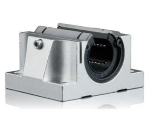
1. Ball Linear Bearings (Recirculating Ball Bearings): These are the most common and versatile type of linear bearing. They operate on the principle of continuous recirculation of balls between the bearing housing and the shaft. This design offers low friction, high precision, and good speed capabilities. Various types are available:
- Compact Type: Ideal for standard applications.
- Open Type: Used with support rails mounted beneath the shaft in situations where the shaft needs to be supported.
- Flanged Type: Features a flanged housing for ease of mounting and a more robust connection.
These bearings typically operate on hardened and ground precision shafts. Their load capacities vary depending on the number, diameter, and contact angle of the balls. Thanks to their low friction coefficients, they provide energy efficiency.
2. Roller Linear Bearings: These offer higher load carrying capacity and greater rigidity compared to ball bearings. They are particularly preferred in applications involving heavy loads and shock loads. Rollers provide a larger contact area than balls, distributing the load over a wider surface.
- Crossed Roller Bearings: Rollers are arranged in a crisscross pattern, allowing them to carry both radial and axial loads with high precision.
- Cylindrical Roller Bearings: Especially suitable for very high radial loads.
These types of bearings are commonly used in high-precision machine tools, robotic arms, and heavy industrial machinery.
3. Profiled Rail Linear Guides: These systems offer the highest precision, rigidity, and load capacity. They consist of a guide rail and one or more carriage blocks that move along this rail. Balls or rollers recirculate within the carriage blocks. Their modular design provides a wide range of products with different sizes and load capacities.
- Ball Profiled Rail Guides: For high speed, precision, and medium-to-high loads.
- Roller Profiled Rail Guides: For very high loads, impact resistance, and rigidity.
They are indispensable in critical applications such as CNC router machines, precision measuring devices, and semiconductor manufacturing equipment.
4. Plain/Sleeve Bearings: These are bearings that operate on a direct contact principle, without rolling elements. They are typically made from self-lubricating polymer materials (such as PTFE, UHMW-PE) or metals like bronze. They are preferred for low-speed applications, highly contaminated environments, vibration absorption, and when seeking economical solutions. Their friction coefficients are higher than those of rolling element bearings, but their maintenance requirements are generally lower. They can be used with stainless steel shafts, especially in environments where hygiene is important, such as the food and pharmaceutical industries, or where aggressive chemicals are present.

Shaft Load Capacities and Calculations
The performance and lifespan of linear bearing systems are directly related to the shaft’s load capacity. Shaft load capacity refers to the maximum load a shaft can bear without bending or permanent deformation. This capacity depends on the shaft’s material, diameter, length, and support method.
Dynamic Load Capacity (C): This is the maximum equivalent dynamic load that a linear bearing can safely carry under nominal operating conditions for a specified lifespan (typically 100 km or 50 million revolutions). This value indicates how much load the bearing can carry while in motion and is used in bearing life calculations.
Static Load Capacity (C0): This is the maximum load that bearings and shafts can withstand without permanent deformation when stationary or operating at very low speeds. It is particularly important for shock loads at standstill or long-term static loads.
Shaft Selection and Sizing Criteria:
- Material: Typically hardened and ground carbon steel (SUJ2/100Cr6) or stainless steel (AISI 440C) is used. Hardness (HRc 60-64) and surface quality (Ra 0.2-0.4 µm) are critically important.
- Diameter: As the load increases, the shaft diameter must also increase. The shaft’s diameter directly affects its resistance to deflection.
- Support Method:
- Cantilever Support: Situations where the shaft is supported at only one or two ends. In this case, the risk of bending is higher, and the load capacity is lower.
- Fully Supported: Situations where the shaft rests on a support rail along its entire length. This prevents shaft bending and provides much higher load capacities.
- Shaft Deflection: Especially for long shafts and precision applications, the amount of deflection of the shaft under its own weight or applied loads must be calculated. The maximum allowable deflection is usually determined by the application’s precision (e.g., 0.05 mm/m).
- Safety Factor (fs): A safety factor must be applied to the load capacity values obtained from theoretical calculations, depending on application conditions (shock loads, vibration, temperature, etc.). A value typically between 1.5 and 3 is used.
Life Calculation: The life of linear bearings is typically calculated using the formula L = (C/P)^3 * 10^5 meters. Here, C is the dynamic load capacity, and P is the equivalent dynamic load. This formula is used to estimate the fatigue life of the bearing, and detailed life calculation methods are usually found in manufacturer catalogs.
| Parameter | Value/Description |
|---|---|
| Bearing Type | Ball Linear Bearing (Compact) |
| Dynamic Load Capacity (C) | 100N – 10000N (Depending on shaft diameter and design) |
| Static Load Capacity (C0) | 150N – 15000N (Depending on shaft diameter and design) |
| Friction Coefficient | 0.001 – 0.005 (Depending on lubrication and load) |
| Max. Speed | 3 m/s – 5 m/s (Depending on shaft diameter and bearing type) |
| Operating Temperature Range | -20°C to +80°C (Standard, different for special types) |
| Shaft Diameter Range | 6 mm – 80 mm (Varies by manufacturer and series) |
| Shaft Surface Hardness | HRc 60-64 (For optimum performance) |
| Application Area | General automation, packaging, assembly machines |

Field Considerations
- Shaft Selection and Preparation: The shaft’s material, surface hardness, surface roughness, and straightness are critically important. High hardness (typically HRc 60-64) and a precisely ground surface (Ra 0.2-0.4 µm) directly affect bearing life and performance. The ends of the shaft should be chamfered and free of sharp edges to prevent damage to the sealing elements during bearing installation. Fully supported shafts provide higher rigidity and precision by minimizing bending, especially for long strokes and heavy loads.
- Mounting Precision and Alignment: One of the most significant factors affecting the life and performance of linear bearing systems is correct installation. The mounting surfaces of bearing blocks or housings must be flat and parallel. Parallelism errors lead to excessive loading on bearings, increased friction, and premature wear. Tolerances are typically at the micron level, and appropriate mounting tools and torque wrenches should be used. In systems using multiple bearing blocks, parallelism and coaxiality between blocks are crucial.
- Lubrication and Maintenance: Regular and correct lubrication of linear bearings reduces friction, prevents wear, and extends their life. The appropriate lubricant (grease or oil) should be selected based on the application’s speed, load, operating environment, and temperature. Many bearings are equipped with sealing elements that retain lubrication for their entire life, but periodic relubrication may be necessary in heavy-duty or high-speed applications. Lubrication schedules should be determined according to manufacturer recommendations and field conditions. In dirty environments, the condition of the sealing elements should be checked frequently.
- Environmental Factors and Protection: Dust, dirt, moisture, water splashes, aggressive chemicals, and extreme temperature variations can negatively affect bearing performance. For such environments, stainless steel bearings, specially coated shafts, high-performance sealing elements (wipers), and protective bellows should be used. Protecting bearing housings and shafts is vital, especially in environments with metal chips.
- Loading Direction and Distribution: The load carrying capacities of linear bearings can vary depending on the direction of the applied load (radial, reverse radial, lateral). These details are specified in manufacturer catalogs. Furthermore, when multiple bearings are used in a system, it must be ensured that the load is evenly distributed among the bearings. Excessive moment loads can cause localized high stresses in bearings, leading to premature failures. Whenever possible, it is recommended to keep the center of gravity of the load between or over the bearings.

Common Problems and Solutions
Common problems related to linear bearings in industrial automation systems and suggested solutions are presented below:
1. Premature Wear and Short Lifespan:
- Problem: Bearings wearing out much earlier than expected, developing play, or making noise.
- Possible Causes: Insufficient or incorrect lubrication, overloading, contamination (dust, chips, etc.), incorrect installation (alignment errors), insufficient shaft surface hardness or roughness.
- Solution: Determine the correct lubricant and lubrication interval. Recalculate the actual loads of the application and review the safety factor. Use sealing elements or protective bellows suitable for the operating environment. Check the shaft’s hardness and surface quality. Adhere strictly to installation instructions and check parallelism/alignment settings.
2. Sticking or Irregular Movement:
- Problem: The bearing system not moving smoothly, experiencing sticking, or showing resistance at certain points.
- Possible Causes: Shaft bending or damage, bearing contamination, installation errors (parallelism or coaxiality issues), damage to the bearing’s internal structure (crushed balls).
- Solution: Inspect the shaft visually and with precision measuring devices. Clean and relubricate the bearings. Check the flatness of mounting surfaces and the alignment of bearings. Replace damaged bearings. If necessary, switch to fully supported shaft systems.
3. Excessive Noise and Vibration:
- Problem: Abnormal sounds (friction, clicking) or noticeable vibrations during operation.
- Possible Causes: Insufficient lubrication, contamination inside the bearing, damage to balls or rollers, installation errors, shaft resonance, overloading.
- Solution: Check lubrication status and relubricate with appropriate lubricant if necessary. Clean the bearings. Replace damaged bearings. Correct installation errors. Review shaft supports or housing design to prevent resonance in the system.
4. Insufficient Load Capacity:
- Problem: Bearings or shafts unable to carry expected loads, leading to deformation or excessive bending.
- Possible Causes: Incorrect calculation of application loads, overlooking sudden shock loads, insufficient safety factor, incorrect bearing type or shaft diameter selection.
- Solution: Recalculate the application’s maximum static and dynamic loads, shock loads, and moment loads in detail. Select a bearing type with higher load capacity (e.g., switching from ball to roller or profiled rail) or a larger diameter shaft. Increase the safety factor. Ensure the shaft is fully supported.
5. Corrosion:
- Problem: Rusting on bearing surfaces or the shaft.
- Possible Causes: Exposure to humid or chemical vapors, unsuitable material selection, insufficient protective lubrication.
- Solution: Use stainless steel bearings and shafts. Apply protective coatings suitable for the environment. Check sealing elements and improve them if necessary. Use special lubricants resistant to moisture and chemicals.
Expert Advice
At the heart of industrial automation systems, linear motion comes to life with the correct selection of bearings and shafts. As detailed in this guide, the variety of linear bearings and shaft load capacities are more than just technical parameters; they directly impact the overall performance, lifespan, and maintenance costs of a system. As an expert engineer, my advice is to seek the “most suitable” solution rather than the “best,” considering the unique dynamics of each project. Evaluating factors such as load, speed, precision, rigidity, environmental conditions, and budget constraints as a whole is key to creating an optimal linear motion system. In particular, accurate calculation of dynamic and static load capacities, shaft deflection analyses, and the application of appropriate safety factors are indispensable for long-lasting and trouble-free systems. Detailed engineering data and calculation methods in manufacturer catalogs will be your most reliable guide in this process. Furthermore, the importance given to mounting precision, regular and correct lubrication, and environmental protection forms the basis for maximizing the performance of even the best-selected components and minimizing unexpected failures. Most problems encountered in the field arise from deviations from these fundamental principles. Therefore, diligence in the design phase will provide significant advantages in operational processes. In the future, linear motion technologies will further develop with sensor-integrated “smart” bearings and AI-supported predictive maintenance systems, but fundamental engineering principles will always remain valid. Remember, correct selection is the foundation of an efficient and reliable automation system.
FAQ
What are linear bearings and how do they function in industrial automation?
Linear bearings are mechanical components that enable precise, low-friction linear motion along a shaft or rail, typically using rolling elements (balls or rollers) or sliding surfaces. They are crucial for the efficiency and repeatability of industrial automation processes.
What are the main types of linear bearings used in industrial applications?
Common types include ball linear bearings (recirculating ball bearings), roller linear bearings, profiled rail linear guides (ball and roller types), and plain/sleeve bearings. Each type offers different characteristics regarding load capacity, precision, and environmental suitability.
How is shaft load capacity defined and what factors influence it?
Shaft load capacity refers to the maximum load a shaft can bear without bending or permanent deformation. It is determined by the shaft's material, diameter, length, and support method (e.g., cantilever vs. fully supported). Dynamic load capacity (C) relates to loads during motion, while static load capacity (C0) refers to loads when stationary.
What are the critical considerations for installing and maintaining linear bearing systems?
Proper shaft selection (material, hardness, surface quality), precise mounting and alignment, regular and correct lubrication, and protection against environmental factors (dust, moisture, chemicals) are critical for maximizing performance and lifespan.
What are common problems with linear bearings and how can they be resolved?
Common issues include premature wear (due to poor lubrication, overloading, contamination), sticking or irregular movement (shaft damage, alignment errors), excessive noise/vibration (contamination, bearing damage), insufficient load capacity (incorrect sizing), and corrosion (environmental exposure). Solutions involve proper selection, maintenance, and adherence to manufacturer guidelines.



