
No products in the cart.
How Automatic Tool Changer (ATC) Systems Work in Industrial CNC Routers
Contents
- Introduction and Technical Analysis of Automatic Tool Changer (ATC) Systems
- Working Principle and Technical Data of Automatic Tool Changer (ATC) Systems
- Automatic Tool Changer (ATC) Systems: Field Considerations
- Automatic Tool Changer (ATC) Systems: Common Problems and Solutions
- Conclusion and Expert Advice on Automatic Tool Changer (ATC) Systems
- FAQ
Introduction and Technical Analysis of Automatic Tool Changer (ATC) Systems
Automatic Tool Changer (ATC) Systems have become an indispensable part of industrial automation and modern manufacturing processes, revolutionizing production efficiency, precision, and flexibility, especially in CNC (Computer Numerical Control) machines. The time loss, risk of human error, and labor costs associated with manual tool changes have been the primary motivation behind the development of ATC systems. These systems enable the automatic and rapid changing of tools required for different operations (milling, drilling, tapping, turning, etc.) in a machining center or turning center, without human intervention. This makes it possible to process complex parts in a single setup, while maximizing production continuity and automation levels. The fundamental technical analysis of ATC systems relies on the integrated operation of mechanical, pneumatic/hydraulic, electrical, and control systems. This complex structure, consisting of a tool magazine, a tool changer arm, and a spindle interface, ensures uninterrupted machine operation by changing tools within milliseconds. This guide aims to provide industrial automation professionals with a comprehensive understanding of the in-depth working principles, technical details, field applications, and solutions to potential problems encountered with ATC systems.
Working Principle and Technical Data of Automatic Tool Changer (ATC) Systems
Automatic Tool Changer (ATC) systems are critical components at the heart of modern CNC machining centers, providing high automation and efficiency. The working principle of these systems involves a series of integrated mechanical, electronic, and software steps. Fundamentally, they automatically manage the process of removing a tool from the spindle, placing it into a specific slot in the tool magazine, and picking up a new tool from the magazine to install it into the spindle.
Key Components:
- Tool Magazine: This is the main unit where tools are stored. It can have different tool capacities (typically 20 to 100+ tools) and configurations. The most common types include chain type, drum type, and disc type magazines. Chain type magazines offer high capacity, while drum type magazines can provide faster access. Each tool has a unique identification number (ID) or position and is tracked by the control system.
- Tool Changer Arm: This arm is the movable mechanism responsible for taking the old tool from the spindle and placing it into its slot in the magazine, and for picking up a new tool from the magazine and installing it into the spindle. It typically has a double gripper structure; one arm holds the old tool while the other holds the new tool, significantly shortening the changeover time. Some simpler systems may feature a single arm or direct spindle-to-magazine changes. The arm’s movement is usually controlled by servo motors, pneumatic actuators, or hydraulic cylinders, supported by precise positioning sensors.
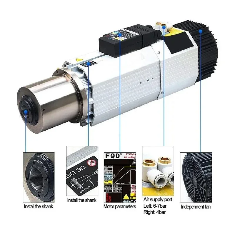
- Spindle: This is the main unit to which the tool is attached and which provides rotational motion during machining. Inside the spindle, there is a hydraulic or pneumatic tool holder mechanism (usually a drawbar system) that securely grips the tool and releases it when needed. This mechanism connects the tool to a tapered seat (e.g., BT, CAT, HSK standards).
- Control System: This is the brain that manages all ATC operations. It is typically performed by the machine’s main CNC control unit or an integrated PLC (Programmable Logic Controller). It receives the tool change command, selects the correct tool from the magazine, synchronizes the movements of the tool changer arm, and controls the opening and closing of the tool holder in the spindle. Feedback from sensors verifies that all steps are completed correctly and safely.
Step-by-Step Working Principle:
- Preparation: When a tool change command (e.g., M06) is detected in the CNC program, the control system determines the position of the new tool to be changed in the magazine. The machine usually moves the spindle to a safe tool change position (Z-axis up, tool change position).
- Tool Selection: The tool magazine brings the desired new tool to the tool changer arm’s access point. This can occur by the magazine rotating or the tool slot moving.
- Releasing the Old Tool: The tool changer arm positions itself to simultaneously grip the old tool in the spindle and the new tool selected from the magazine. The drawbar in the spindle retracts pneumatically or hydraulically, releasing the old tool’s grip.
- Tool Change: The tool changer arm rapidly rotates 180 degrees, placing the old tool into an empty slot in the magazine and inserting the new tool into the spindle’s tapered seat. This stage is the most critical and time-optimized part of the ATC system.
- Locking the New Tool: Once the new tool is placed in the spindle, the drawbar in the spindle pushes forward to securely lock the tool. This locking is usually verified by a sensor.
- Arm Retraction: The tool changer arm safely retracts from the spindle and magazine, returning to its starting position.
- Continuation: The machine is ready to continue the machining operation with the new tool. This process typically completes within a few seconds, minimizing production interruption.
Engineering Data and Application Areas:
The performance of ATC systems is measured by parameters such as tool change time (chip-to-chip time), tool capacity, maximum tool weight, and repositioning accuracy. High-performance systems can achieve short changeover times of 1-3 seconds. Application areas are extremely broad: they are used for automatic tool or fixture changes in various industrial applications such as CNC milling machines, turning centers, multi-axis machining centers, drilling machines, and even some welding or assembly robots. In sectors like aerospace, automotive, mold making, medical, and general machine manufacturing, the role of ATC systems is indispensable for producing complex parts with high precision and efficiency. Especially within the scope of Industry 4.0 and smart manufacturing concepts, integrated ATC systems with tool management and predictive maintenance capabilities stand out as a key component in the digitalization of production processes.
| Parameter | Value/Description |
|---|---|
| Tool Change Time (Chip-to-Chip) | Average 3 – 8 seconds (Can be under 1 second in high-speed systems) |
| Tool Capacity | 20 – 120+ tools (Varies by machine type and magazine design) |
| Maximum Tool Weight | 3 kg – 30 kg (Depends on the carrying capacity of the tool changer arm) |
| Maximum Tool Diameter | 75 mm – 300 mm (Can be increased by clearing adjacent tools) |
| Repeatability Accuracy | ±0.003 mm – ±0.005 mm (Depends on spindle taper and tool holder quality) |
| Drive System | Servo Motor (High speed and precision), Pneumatic/Hydraulic Cylinders (Simpler systems) |
| Control Interface | CNC Control Unit (Fanuc, Siemens, Heidenhain, etc.) or Integrated PLC |
Automatic Tool Changer (ATC) Systems: Field Considerations
- Correct Tool Loading and Management: It is essential to load tools into the correct slots in the magazine, with the right orientation, and in a clean condition. Ensure that tool holders (BT, CAT, HSK tapers) and pull studs are clean. Dirty or damaged tools can lead to jamming, loss of precision, or even tool drops during tool changes. Additionally, ensure that the weight and length limits of each tool are adhered to, and that unbalanced or excessively long tools are assigned to special slots. Monitoring tool life and timely replacement of worn tools are critical for production quality and machine health.
- Periodic Maintenance and Cleaning: ATC systems are complex structures with many moving parts and sensors. Regular lubrication and cleaning of the tool changer arm’s joints, the magazine’s rotation mechanisms, and the spindle’s drawbar system are required. In particular, chips, coolant, and dirt accumulation can lead to incorrect sensor readings or mechanical jamming. Periodically clean and calibrate sensors (proximity sensors, position sensors), and check the sealing of pneumatic or hydraulic hoses and connections.
- Work Safety Procedures: The tool change area is a hazardous zone when the machine is operating. Absolutely no intervention should be made in this area during the machine’s tool change cycle. Regularly check the accessibility and functionality of emergency stop buttons. During maintenance or troubleshooting, ensure that the machine’s power is completely cut off and that lockout/tagout (LOTO) procedures are applied to prevent unexpected movements. Operators must fully understand the safety features and potential risks of ATC systems.
- CNC Programming and Tool Offsets: It is vital that tool change commands (M06) are called at the correct positions and with the correct tool numbers. Correctly setting and updating tool offsets (length and diameter compensation) directly affects machining precision. Incorrect offsets can lead to dimensional errors in the machined part or tool breakage. Some advanced systems may have sensors that automatically measure tool length; calibration and cleaning of these sensors should also be performed regularly.
- Control of Environmental Factors: Chips, dust, humidity, and temperature fluctuations can negatively affect the performance of ATC systems. Especially in open-type magazines, chip accumulation can cause jamming. Keeping the machine environment clean, correctly directing coolant, and equipping the magazine area with protective covers when necessary will increase the system’s lifespan and reliability.
Automatic Tool Changer (ATC) Systems: Common Problems and Solutions
ATC systems, due to their complex structure, can occasionally encounter various problems. Rapid and accurate diagnosis and resolution of these issues are critical to minimizing production downtime.
- Tool Drop or Misalignment: This is one of the most critical and potentially costly problems. It usually occurs due to insufficient clamping by the spindle’s tool holder (drawbar), wear/misadjustment of the tool changer arm, improper seating of the tool in the magazine or spindle, or contamination/damage to the tool flange.
Solution: First, check the hydraulic or pneumatic pressure and functionality of the spindle’s tool holder (drawbar). Adjust pressure values or replace faulty valves if necessary. Check the mechanical adjustments of the tool changer arm, especially rotation angles and gripping force, and calibrate according to factory settings. Verify the cleanliness and integrity of tool holders and flanges. Replace worn or deformed tool holders or flanges. Ensure sensors are working correctly and are not contaminated.
- Increased or Slowed Tool Change Time: Tool changes that take longer than normal reduce production efficiency. This can be caused by pressure drops in pneumatic or hydraulic systems, servo motor failures, mechanical friction, lack of lubrication, or errors in control system parameters.
Solution: Check the pressure and flow rates of pneumatic/hydraulic systems, clean or replace filters. Diagnose the condition of servo motors and drives, check connections or replace the motor if necessary. Lubricate all moving parts of the tool changer arm and magazine mechanism to reduce mechanical friction. Check and optimize tool change speed parameters in the CNC control system.
- Magazine Jamming or Tool Selection Error: Situations such as the magazine not rotating, failing to find the correct tool, or the tool arm being unable to pick up a tool from the magazine are common problems. Chip accumulation, damaged tool slots, magazine motor failure, or position sensor errors are the main causes.
Solution: Clear the magazine area and tool slots of chips and dirt. Repair or replace damaged tool slots. Check the electrical connections and operation of the magazine motor (usually a servo or stepper motor). Check the cleanliness, adjustment, and functionality of magazine position sensors (encoder or proximity sensors), calibrate or replace if necessary. Ensure that tool numbers in the CNC program match the physical locations in the magazine.
- Sensor Failures: When sensors (proximity sensors, optical sensors, limit switches) that verify the position of the tool changer arm, the presence of a tool in the spindle, or the placement of a tool in the magazine fail or become contaminated, the ATC system stops or operates incorrectly.
Solution: Check the wiring, connections, and power supply of the suspected faulty sensor. Clean the sensor’s working surface. Ensure the sensor is adjusted at the correct distance and angle. If necessary, test the sensor with a multimeter or oscilloscope to confirm its operation, and replace it if faulty. Examine CNC error codes to identify which sensor is causing the problem.
- Control System Communication Errors: Disruptions in communication between the ATC unit and the main CNC control unit can cause the system to freeze or exhibit unexpected behavior.
Solution: Check communication cables (Ethernet, Profibus, CanOpen, etc.) and connectors. Analyze error messages in the CNC control unit. Check the PLC program to ensure that logic steps related to the ATC are working correctly. If necessary, verify communication protocol settings between the control unit and the ATC.
Conclusion and Expert Advice on Automatic Tool Changer (ATC) Systems
Automatic Tool Changer (ATC) systems are a cornerstone of modern industrial automation and high-efficiency manufacturing. These systems offer significant competitive advantages to businesses by increasing the speed, flexibility, and precision of production processes. By eliminating the time losses and human errors associated with manual tool changes, they provide an uninterrupted workflow, especially in complex and multi-stage machining operations. Our field experience shows that to fully benefit from an ATC system’s potential and minimize malfunctions, not only correct initial installation but also a continuous and conscious maintenance strategy is vital. Regular cleaning, periodic lubrication, sensor calibrations, and checking mechanical adjustments extend the system’s lifespan and prevent unexpected downtime. Furthermore, it is essential for operators and maintenance personnel to receive continuous training to thoroughly understand the working principles, safety procedures, and basic troubleshooting methods of ATC systems. In the era of Industry 4.0 and digitalization, ATC systems are moving beyond mere mechanical functions, becoming integrated with smart sensors, data analytics, and even AI-powered predictive maintenance algorithms. This allows for tool wear or potential malfunctions to be detected and proactively addressed long before they occur. It is clear that in the future, ATC systems will continue to become faster, more flexible, and smarter, contributing to the autonomization of production processes and reaching new peaks of efficiency. Therefore, it is indispensable for every professional in the industrial automation sector to grasp the intricacies of this critical technology and adopt best practices for sustainable success. As expert advice, we strongly recommend adhering to the manufacturer’s maintenance manuals, using original spare parts, and keeping your systems up-to-date by closely following technological advancements to maintain ATC system performance at the highest level.
FAQ
What is an Automatic Tool Changer (ATC) system?
An Automatic Tool Changer (ATC) system in a CNC machine is a mechanism that automatically selects and replaces cutting tools from a tool magazine into the machine's spindle without human intervention. This process significantly enhances production efficiency, precision, and automation.
What are the main components of an ATC system?
Key components include the tool magazine (stores tools), the tool changer arm (moves tools between magazine and spindle), the spindle (holds and rotates the tool), and the control system (manages the entire ATC operation).
How does an ATC system operate step-by-step?
The ATC system receives a tool change command from the CNC program. The tool magazine rotates to position the new tool. The tool changer arm simultaneously grips the old tool from the spindle and the new tool from the magazine, rotates 180 degrees, exchanges them, and then retracts, allowing machining to resume with the new tool.
What are common problems encountered with ATC systems and their solutions?
Common issues include tool drops or misalignment, increased tool change time, magazine jamming, tool selection errors, sensor failures, and control system communication problems. These can often be resolved with proper maintenance, calibration, and component replacement.
What are the critical maintenance practices for ATC systems?
Regular maintenance, including cleaning, lubrication, sensor calibration, and checking mechanical adjustments, is crucial. Ensuring correct tool loading, adhering to safety procedures, and accurate CNC programming with updated tool offsets also contribute to optimal performance.



