No products in the cart.
How to Adjust Rack and Pinion Gear Backlash
Contents
Properly adjusting the backlash in a rack and pinion system is crucial for the precision, lifespan, and performance of industrial machinery. This guide explains the importance of backlash, common adjustment methods using eccentric bushings or adjustable plates, and the technical considerations for achieving optimal results in CNC routers and automation applications.
Mermak CNC Technical Guide
Practical notes for CNC router, automation and industrial motion systems.
Understanding Rack and Pinion Gear Backlash
In industrial automation and linear motion systems, rack and pinion systems are frequently employed for their precision and reliability. A critical adjustment for their optimal performance is the gear backlash, also known as play. Gear backlash refers to the small clearance between meshing teeth when gears do not fully engage. This manifests as a slight delay or free movement during direction changes. For instance, when a pinion reverses direction on a rack, a backlash means the pinion must rotate a small amount before engaging the rack and initiating movement. This can lead to positioning errors, vibrations, noise, and impact loads during acceleration/deceleration, particularly in applications requiring precise positioning like robotic arms, CNC machines, and automated production lines. Therefore, correctly adjusting rack and pinion backlash is vital for the overall performance, longevity, and accuracy of the system. The goal is to achieve minimal backlash for maximum precision without causing binding.
Principle of Operation and Technical Data
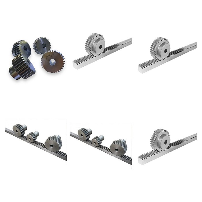
Adjusting rack and pinion backlash is achieved through various methods depending on the system’s mechanical design and the required precision. The fundamental principle is to precisely control the center distance between the pinion and the rack to determine how tightly the teeth mesh. This adjustment aims to prevent the gears from meshing too tightly (binding) or too loosely (excessive backlash), both of which negatively impact system performance.
Primary Adjustment Mechanisms:
- Eccentric Bushings or Flanges: A common method involves an eccentric bearing or flange for the pinion. Rotating this bushing alters the pinion’s center distance relative to the rack. Once adjusted, it’s secured with locking mechanisms (usually screws). This offers fine, continuous adjustment.
- Adjustable Mounting Plates or Slides: The plate or slide mounting the pinion or gearbox can be designed to move relative to the rack. These are typically adjusted using screws and bolts to move the pinion forward or backward, setting the backlash. After adjustment, bolts are tightened to secure the system.
- Shims: In less precise applications or specific mounting scenarios, shims of varying thicknesses can be added or removed from beneath the pinion bearing or mounting surface to adjust the center distance. This method is generally for coarser adjustments and requires disassembly.
- Preloaded (Anti-Backlash) Pinions: For high-precision applications, specially designed preloaded pinions are used to eliminate mechanical backlash. These often consist of two parts that are slightly rotated against each other, typically via a spring, to constantly apply opposing force to the rack teeth. This ensures teeth are always engaged, effectively zeroing backlash. While more complex and costly, they offer superior precision.
Adjustment Process and Measurement Techniques:
Adjustment is typically performed using a dial indicator. The indicator is placed on a pinion tooth or a fixed point near the gear mesh. The pinion is then rotated slightly back and forth while the rack is held stationary. The reading on the dial indicator quantifies the backlash. The ideal backlash value is determined by the gear manufacturer’s specifications, often dependent on the gear module, material thermal expansion, and application requirements. Generally, backlash should allow for a minimal oil film between teeth without compromising system accuracy. Overly tight adjustment leads to overheating, friction, and premature wear, while excessive backlash causes impact loads and loss of precision.
| Parameter | Value/Description |
|---|---|
| Ideal Backlash Tolerance | Typically 2% to 5% of the tooth module (e.g., 0.04 – 0.10 mm for Module 2). Consult manufacturer specifications. |
| Measurement Method | Dial indicator on gear teeth or feeler gauge between gear and rack. |
| Adjustment Mechanism | Eccentric bushings, adjustable mounting plates, shims, or preloaded pinions. |
| Material Influence | Materials with higher thermal expansion (e.g., aluminum) may require more backlash. |
| Application Areas | CNC machines, robotic arms, linear actuators, automation lines, machine tools. |
| Periodic Check | Every 6 months or annually, depending on operating hours, load cycles, and environmental conditions. Adjust if necessary. |
| Recommended Lubrication | Industrial grease or gear oil suitable for the gear type and operating conditions. Reduces wear and extends life. |
Field Considerations for Adjustment
- Safety Precautions: Before starting any adjustment, de-energize the machine, apply lockout/tagout procedures, and ensure all moving parts have completely stopped. Safety is paramount.
- Manufacturer Specifications: Always consult the technical documentation and backlash tolerance values provided by the rack and pinion system manufacturer before beginning adjustments. Each system has unique optimal backlash settings.
- Correct Measurement Tools: Use a calibrated dial indicator or precise feeler gauges to accurately measure backlash. Mount the dial indicator perpendicular to the pinion tooth and rotate the pinion back and forth to read the backlash. Repeat measurements at different points for consistency.
- Step-by-Step Adjustment and Verification: Make adjustments in small increments. For example, slightly rotate the eccentric bushing or tighten/loosen an adjustment screw by a quarter turn. Re-measure the backlash after each adjustment. The objective is to achieve minimal backlash without causing binding.
- Prevent Binding: Ensure the gears do not bind during adjustment. Manually move the pinion along the rack or use the motor at low speed to check for any sticking, excessive friction, or abnormal resistance. Binding can lead to overheating, premature wear, or even tooth breakage.
- Tightening Torques: Once adjusted, tighten the eccentric bushings or mounting bolts to the manufacturer’s specified torque values. Improper tightening can alter the adjustment or cause component damage.
- Lubrication: After adjustment, ensure the system is properly lubricated according to the manufacturer’s recommendations. This is crucial for smooth operation and longevity.
Properly setting the backlash in your rack and pinion system is a critical maintenance task that directly impacts the accuracy and efficiency of your industrial CNC router machine or other automated equipment. By following these guidelines, you can ensure your linear motion systems operate at peak performance.
For expert advice or to discuss your specific application needs for high-precision linear motion components, request a quote on WhatsApp today.
Related product categories: Genel · Mekanik · Düz Diş Kremayer Dişli Çeşitleri