No products in the cart.
How Much Misalignment Can a Flexible Coupling Compensate For?
Contents
- Understanding Flexible Couplings and Their Role in Industrial Systems
- How Much Misalignment Can a Flexible Coupling Compensate For? Technical Data and Principles
- Key Considerations for Industrial Applications
- Understanding Flexible Couplings and Misalignment Compensation
- Operating Principles and Technical Data
- Field Considerations for Flexible Couplings
Mermak CNC Technical Guide
Practical notes for CNC router, automation and industrial motion systems.
Understanding Flexible Couplings and Their Role in Industrial Systems
In industrial automation and mechanical engineering, couplings are essential components used to connect two rotating shafts. While ideally, these shafts would be perfectly aligned, real-world applications often present challenges such as manufacturing tolerances, assembly errors, thermal expansion, foundation settling, and dynamic loads. These factors lead to inevitable misalignment between shafts. This is where flexible couplings play a critical role. They absorb these misalignments, enabling torque to be transmitted safely and efficiently from one shaft to another, thereby enhancing system performance and extending equipment lifespan.
Flexible couplings are designed to compensate for three primary types of shaft misalignment:
- Radial Misalignment (Offset Misalignment): Occurs when the axes of two shafts are parallel but not concentric. There is a lateral distance between the shaft centers.
- Angular Misalignment: Happens when the axes of two shafts intersect at an angle, meaning they are not collinear even if they meet at a point.
- Axial Misalignment: Refers to the condition where the shafts move towards or away from each other along their axis. This is often caused by thermal expansion or axial shaft movement.
By compensating for these misalignments, flexible couplings reduce stress on bearings, seals, shafts, and other machine components, preventing premature failures, lowering maintenance costs, and improving energy efficiency. This capability makes them indispensable in high-speed, high-torque, and continuous-operation industrial applications.
How Much Misalignment Can a Flexible Coupling Compensate For? Technical Data and Principles
The misalignment compensation capacity of a flexible coupling is largely dependent on its design, materials, and size. Different coupling types offer varying tolerances for different types of misalignment. Here’s an overview of common flexible coupling types and their general misalignment capabilities:
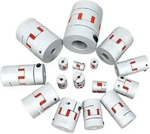
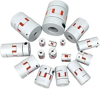
- Elastomeric Couplings (Jaw, Tyre, Bush): These couplings feature an intermediate element made of rubber, polyurethane, or other elastomer. They are known for their high vibration damping and shock absorption capabilities.
- Radial Misalignment: Typically between 0.1 mm and 0.5 mm.
- Angular Misalignment: Typically between 0.5 degrees and 2 degrees.
- Axial Misalignment: Typically between 1 mm and 5 mm.
- Advantages: Excellent vibration damping, electrical insulation, cost-effectiveness.
- Disadvantages: Limited in high-torque applications, elastomer lifespan affected by temperature and chemicals.
- Disc Couplings (Diaphragm, Disc): Composed of thin disc packs, usually made of stainless steel. They offer high torque capacity, require no maintenance, and can operate at high speeds.
- Radial Misalignment: Typically between 0.05 mm and 0.2 mm (single disc); higher in double-disc types.
- Angular Misalignment: Typically between 0.25 degrees and 1 degree.
- Axial Misalignment: Typically between 0.5 mm and 2 mm.
- Advantages: High torque, maintenance-free operation, high speed capability, thermal stability.
- Disadvantages: Limited vibration damping, sensitive to shock loads.
- Gear Couplings: Consist of internal and external gear teeth, typically lubricated with oil or grease. They can transmit very high torques and are used in heavy-duty industrial applications.
- Radial Misalignment: Typically between 0.05 mm and 0.15 mm.
- Angular Misalignment: Typically between 0.5 degrees and 1.5 degrees.
- Axial Misalignment: Limited, usually around 0.1 mm.
- Advantages: Very high torque capacity, compact design.
- Disadvantages: Requires maintenance (lubrication), poor vibration damping, potential for wear.
- Bellows Couplings: Feature a bellows structure, often made of stainless steel. They are used in applications requiring high precision and low inertia.
- Radial Misalignment: Typically between 0.05 mm and 0.2 mm.
- Angular Misalignment: Typically between 0.5 degrees and 2 degrees.
- Axial Misalignment: Typically between 0.5 mm and 3 mm.
- Advantages: High precision, low inertia, maintenance-free.
- Disadvantages: Lower torque capacity compared to other types, potentially higher cost.
- Universal Joint Couplings: Used to accommodate larger angular misalignments, but they do not transmit torque at a constant velocity (causing speed fluctuations).
- Angular Misalignment: Up to 10 degrees or more (single joint); even more with double joints.
- Other Misalignments: Radial and axial compensation is typically indirect.
- Advantages: Accommodates very high angular misalignment.
- Disadvantages: Does not provide constant velocity torque transmission, can induce vibration.
These values are general guidelines, and specific tolerances can vary significantly between manufacturers and models. Always consult the manufacturer’s technical data sheets and consider the application’s torque, speed, operating temperature, and environmental conditions when selecting a coupling. It’s crucial to remember that flexible couplings compensate for misalignment; they do not replace the need for good initial alignment. The better the initial alignment, the longer the coupling’s life and the more efficient the system’s operation.
| Parameter | Value/Description |
|---|---|
| Coupling Type | Elastomeric (Jaw, Tyre) |
| Radial Misalignment Tolerance | 0.1 mm – 0.5 mm (varies by type and size) |
| Angular Misalignment Tolerance | 0.5° – 2° (varies by type and size) |
| Axial Misalignment Tolerance | 1 mm – 5 mm (varies by type and size) |
| Typical Applications | Pumps, fans, compressors, conveyors, generators, general industrial drives |
| Material Properties | Rubber, polyurethane, nylon (elements); steel, cast iron, aluminum (hubs) |
| Vibration Damping Capacity | High (especially elastomeric types) |
| Operating Temperature Range | -30°C to +100°C (material dependent) |
| Maintenance Requirement | Low to medium (periodic inspection/replacement of elastomeric elements) |
Key Considerations for Industrial Applications
- Proper Coupling Selection and Sizing: The flexible coupling’s misalignment compensation capability must align with the application’s torque, speed, operating temperature, environmental conditions, and the expected degree of misalignment. The coupling’s nominal torque, peak torque, and maximum speed ratings must meet the driven system’s requirements. An incorrectly sized coupling can lead to premature failure or inadequate misalignment compensation. For instance, gear couplings might be suitable for high-torque, low-speed applications, while bellows or disc couplings may be preferred for high-speed, precision servo systems.
- Achieve the Best Possible Initial Alignment: While flexible couplings compensate for misalignment, this does not negate the importance of good initial alignment. The closer the shafts are initially aligned, the less stress the coupling experiences, leading to a longer service life and improved system efficiency. Misalignment beyond the coupling’s specified limits can cause excessive wear, vibration, and potential failure of both the coupling and connected components. Regular checks and adjustments are recommended, especially in systems subjected to significant thermal variations or foundation shifts.
Choosing the right flexible coupling is crucial for the longevity and efficiency of any rotating machinery. By understanding the different types of misalignments and the compensation capabilities of various couplings, engineers can make informed decisions that optimize system performance and reduce operational costs.
For industrial CNC router machines, servo systems, and other precision equipment, ensuring proper shaft alignment and selecting the correct coupling is paramount. This not only protects expensive components like the spindle motor and servo drives but also guarantees the accuracy and reliability of the manufacturing process.
Need to ensure optimal power transmission and minimize wear in your industrial machinery?
Request a quote on WhatsApp today and let our experts help you find the perfect coupling solution for your application.
Related product categories: Genel · 40 mm Kaplin GS19 · Krom Kaplı Ayak
Understanding Flexible Couplings and Misalignment Compensation
In industrial automation and mechanical engineering, couplings are essential components used to connect two rotating shafts, facilitating power transmission. Ideally, all shafts would be perfectly aligned. However, in real-world industrial settings, manufacturing tolerances, assembly errors, thermal expansion, foundation settling, and dynamic loads inevitably lead to some degree of misalignment between shafts. This is where flexible couplings play a crucial role. Designed to absorb these misalignments, dampen vibrations, and extend the lifespan of connected equipment, flexible couplings are specialized mechanical components that ensure smooth system operation.
The primary function of a flexible coupling is to safely compensate for these small but unavoidable alignment differences between shafts. The extent to which a coupling can achieve this compensation varies significantly based on its type, design, materials used, and size. There are three main types of shaft misalignment:
- Radial Misalignment (Parallel Misalignment): Occurs when the centerlines of two shafts are parallel but not concentric, meaning they are offset laterally.
- Angular Misalignment: Occurs when the centerlines of two shafts intersect at a point but are at an angle to each other, causing one or both shafts to be tilted.
- Axial Misalignment (End Float): Occurs when the centerlines of two shafts are concentric but they are displaced from each other along the axial direction (lengthwise).
Flexible couplings are engineered to absorb each of these misalignments to varying degrees. By doing so, they reduce undue stress on critical components like motors, gearboxes, pumps, and compressors, thereby extending the life of bearings and seals and minimizing energy losses. Selecting the correct flexible coupling not only prevents failures but also significantly enhances operational efficiency and reliability.
Operating Principles and Technical Data
The ability of flexible couplings to compensate for misalignment stems from their internal structures, which often incorporate elastomeric elements, metal discs, gear mechanisms, or metal bellows. Each coupling type manages different types of misalignment and load conditions with varying degrees of effectiveness. Here are some common types of flexible couplings and their general compensation capabilities:
- Elastomeric Couplings (Jaw, Tyre, Bush, Spider): These couplings excel at damping shock loads and vibrations. They typically feature an intermediate element (e.g., a spider, tire, or bush) made from materials like rubber, polyurethane, or nylon.
- Radial Misalignment: Generally between 0.2 mm and 1 mm. Tire-type couplings can accommodate higher tolerances (2-5 mm).
- Angular Misalignment: Typically from 0.5° to 2°.
- Axial Misalignment: Usually between 1 mm and 5 mm.
These couplings are popular due to their low maintenance requirements, electrical insulation properties, and relatively low cost.
- Disc Couplings (Diaphragm, Disc Pack): Utilizing stainless steel disc packs or diaphragms, these couplings offer high torque capacity and torsional stiffness while compensating for shaft misalignment through the flexibility of the discs. They are ideal for high-speed and high-torque applications.
- Radial Misalignment: Generally between 0.1 mm and 0.5 mm.
- Angular Misalignment: Typically from 0.5° to 1.5°.
- Axial Misalignment: Usually between 1 mm and 3 mm.
They provide maintenance-free and long-lasting solutions.
- Gear Couplings: These operate with internal and external gear teeth, offering high torque transmission and a compact design. The rolling motion of the gear teeth allows them to compensate for misalignment. They require lubrication.
- Radial Misalignment: Generally between 0.05 mm and 0.2 mm (requiring very precise alignment).
- Angular Misalignment: Typically from 0.5° to 1.5°.
- Axial Misalignment: Limited, ranging from 0.5 mm to 2 mm depending on gear backlash.
They carry a risk of gear wear under overload conditions.
- Grid Couplings: Known for their high torque capacity and vibration damping capabilities, using a spring steel grid element.
- Radial Misalignment: Generally between 0.1 mm and 0.5 mm.
- Angular Misalignment: Typically from 0.5° to 1°.
- Axial Misalignment: Usually between 1 mm and 3 mm.
Preferred for heavy-duty applications.
- Bellows Couplings: Commonly used in precision control systems and servo motor applications. Their metal bellows structure offers very low inertia and high precision.
- Radial Misalignment: Generally between 0.01 mm and 0.2 mm (very precise).
- Angular Misalignment: Typically from 0.1° to 0.5°.
- Axial Misalignment: Usually between 0.5 mm and 2 mm.
They can be expensive but are indispensable where precision is paramount.
The misalignment compensation capacity of a coupling is also influenced by factors such as shaft rotational speed (RPM), transmitted torque, ambient temperature, and the coupling’s size. Higher speeds and torques increase stress on the coupling, thereby reducing the amount of misalignment it can compensate for. Therefore, all these operating conditions must be considered when selecting a coupling.
| Parameter | Value/Description |
|---|---|
| Misalignment Type | Description |
| Radial Misalignment (mm) | 0.1 mm – 5 mm (Varies by coupling type; disc couplings are low, rubber types are high) |
| Angular Misalignment (Degrees) | 0.1° – 3° (Bellows couplings are low, elastomeric types are high) |
| Axial Misalignment (mm) | 0.5 mm – 10 mm (Gear couplings are low, elastomeric types are high) |
| Coupling Type Influence | Elastomeric > Rubber > Grid > Disc > Gear > Bellows (General flexibility order) |
| Material Influence | Rubber/Polyurethane (more flexible), Steel/Aluminum (more rigid) |
| Temperature Effect | High temperatures reduce the life and flexibility of elastomeric elements. |
| Speed and Torque Effect | High speed and torque reduce the amount of compensable misalignment. |
Field Considerations for Flexible Couplings
- Correct Coupling Selection and Sizing: Beyond misalignment compensation, factors such as maximum transmissible torque, operating speed, ambient temperature, chemical exposure, and vibration damping needs must be considered. Manufacturer catalog data and selection charts are critical at this stage. Selecting a coupling that is too large or too small will negatively impact performance.
- Initial Alignment and Tolerances: While flexible couplings compensate for misalignment, this does not mean shafts can be installed with poor alignment. Operating within the coupling’s maximum compensation limits shortens its lifespan and increases energy losses. Therefore, using modern tools like laser alignment devices to bring shafts as close to perfect alignment as possible is recommended to extend the life of the coupling and connected equipment. It is generally advised to operate within 25-50% of the coupling’s compensation capacity.
- Installation and Removal Procedures: Proper installation of couplings is vital for their performance and longevity. Ensure shafts are clean and free of burrs. Use appropriate tools for installation and avoid hammering or forcing the coupling, which can damage its components. Follow manufacturer guidelines for torque specifications if applicable.
- Maintenance and Inspection: Regularly inspect couplings for signs of wear, cracking, or material degradation, especially in elastomeric elements. For lubricated couplings like gear couplings, adhere to the recommended lubrication schedule. Listen for unusual noises that might indicate excessive vibration or wear.
By understanding the capabilities and limitations of different flexible coupling types and adhering to best practices in selection, installation, and maintenance, you can ensure the reliable and efficient operation of your industrial machinery. Choosing the right coupling is a critical step in preventing costly downtime and extending the service life of your valuable equipment.
For expert advice on selecting the ideal flexible coupling for your specific CNC router machine or industrial CNC router application, or to discuss your motion control needs involving spindle motors, servo drives, or linear guide rails, contact us today. We can help you find the perfect solution to optimize your system’s performance and durability.
Ready to ensure your machinery runs smoothly? Request a quote on WhatsApp for the best flexible coupling solutions!
Explore our range of mechanical components, including high-quality couplings, to enhance your industrial systems.
Related product categories: Genel · 40 mm Kaplin GS19