
No products in the cart.
GRBL Control Board Wiring Diagram and Software Installation for Industrial CNC
Contents
GRBL Control Board Wiring Diagram and Software Installation: Field Guide and Technical Article


Introduction and Technical Analysis
In today’s rapidly evolving industrial automation landscape, cost-effective and flexible solutions for applications requiring precise motion control are paramount. In this context, GRBL (G-code Ripper / B-Line) stands out as a popular open-source firmware, particularly for CNC (Computer Numerical Control) machines, laser cutters, and even some prototype 3D printers. Loaded onto an Arduino Uno or a similar microcontroller board, GRBL offers the ability to interpret standard G-code commands and control stepper motors and other peripheral units. This comprehensive guide aims to provide industrial automation professionals with an expert perspective on GRBL control board hardware wiring diagrams, software installation processes, technical details, and solutions for potential field issues. Understanding the fundamental principles of GRBL is critically important for system integrators and maintenance engineers. The cost advantage and flexibility provided by GRBL enable small and medium-sized enterprises to accelerate their automation processes, while also increasing its preference for prototyping and specialized tasks in large-scale industrial applications. The open-source nature of the system offers continuous community support and a vast knowledge base, making it easier for users to find quick solutions to problems they encounter. This guide will provide practical information on how to set up and operate GRBL reliably and efficiently in industrial environments.
Operating Principle and Technical Specifications
GRBL primarily functions as a G-code interpreter and motion controller. It receives G-code commands sent via a serial port (USB) from a computer or another control unit, converting them into step and direction signals that the microcontroller can understand. These signals are transmitted to stepper motor drivers (e.g., A4988, DRV8825) located on a breakout board like a CNC Shield. The drivers use these signals to precisely move the connected stepper motors in the desired direction and amount. GRBL also manages the inputs and outputs of various peripheral units such as limit switches, emergency stop (E-stop) buttons, spindle control (PWM for speed and direction), and probes (for workpiece zeroing). Thanks to this integrated control capability, complex motion profiles and operations can be accurately performed even with low-cost hardware. The core of GRBL includes a high-performance stepper motor control algorithm. This algorithm manages acceleration and deceleration ramps to ensure smooth and vibration-free movement of the motors. This helps achieve higher quality results, especially in high-speed cutting or machining operations, by reducing stress on the material. Despite the limited resources on the microcontroller, GRBL’s optimized code structure offers precise control up to thousands of steps per second. Furthermore, GRBL’s configuration settings ($ commands) allow users to easily adjust parameters such as steps/mm ratio, maximum speed, acceleration, limit switch logic, and many others specific to their application. This flexibility facilitates adaptation to different mechanical setups and motor types. In industrial applications, a stable power supply and protection against electrical noise are vital for the reliability of GRBL-based systems. Proper driver selection and current adjustment are also critical factors for efficient motor operation and preventing overheating. GRBL is recognized as a cost-effective and high-performance solution, especially in prototyping, education, hobby projects, and specific industrial automation niches.
| Parameter | Value/Description |
|---|---|
| Supported Axis Count | 3 Axes (X, Y, Z) standard, 4th axis (A) support in some derivatives |
| Maximum Step Rate | ~30,000 steps/second (for Arduino Uno, depends on processor speed) |
| Microcontroller | Arduino Uno R3 (ATmega328P) or compatible boards |
| Compatible Stepper Motor Drivers | A4988, DRV8825, LV8729, TMC2208/2209 (compatible pin structure with CNC Shield) |
| Input Voltage (CNC Shield) | 12V – 36V DC (According to driver and motor requirements, check manufacturer datasheet values.) |
| Communication Port | USB (Serial Port Emulation) |
| Supported G-code Standard | RS274/NGC compatible basic G-code commands (G0, G1, G2, G3, M3, M5 etc.) |
| Limit Switch Inputs | X+, Y+, Z+ (Normally NC – Normally Closed connection is preferred) |
| Spindle Control | PWM (Pulse Width Modulation) for speed control, On/Off, Direction (DIR) |
Field Considerations
- Wiring Standards and Shielding: Electrical noise (EMI/RFI) is inevitable in industrial environments. High-current carrying and switching signal lines, such as stepper motor cables, should be kept separate from control signal cables (limit switch, probe), and shielded cables should be used where possible. Grounding the shield at a single point is critical to prevent ground loops. Cable cross-sections should be selected according to the current to be carried and the cable length (AWG standards).
- Power Supply and Grounding: A stable and noise-free power supply is vital for the GRBL control board (Arduino) and motor drivers. Using a separate power supply for motor drivers can isolate the Arduino’s power from motor noise. Proper grounding of the entire system is essential for both safety and signal integrity. The ground line resistance should be low, and all equipment should be connected to a common grounding point.
- Limit Switches and Emergency Stop (E-stop): Limit switches are used to prevent the machine from exceeding its mechanical boundaries. Normally Closed (NC) contact switches are generally preferred because in the event of a cable break or loosening, the system automatically gives a “limit exceeded” warning and stops, which is a safer approach. The emergency stop button should be designed as hardware and connected in a way that can directly cut off the power supply to the motor drivers or the main power source. This ensures the machine stops even if the software locks up.
- Stepper Motor Driver Settings: The current setting of stepper motor drivers (A4988, DRV8825, etc.) directly affects the motor’s torque, heating, and lifespan. The current should be set according to the motor’s nominal current value; excessive current can lead to motor overheating and damage, while insufficient current can cause the motor to skip steps. Microstepping settings are also important for balancing precision and speed; typically 1/8 or 1/16 microstepping is a good starting point for industrial applications.
- Cooling and Environmental Conditions: Stepper motor drivers and motors, especially those operating with high current, can heat up. Passive (heat sink) or active (fan-based) cooling solutions should be considered for drivers. Ensuring that the environment where the control board and drivers are located is free from dust, moisture, and excessive temperatures extends the life of electronic components and increases system reliability. Appropriate ventilation and filtering should be provided in industrial panels.
GRBL Software Installation and Settings
Loading GRBL firmware onto an Arduino board and then calibrating the system are among the most critical steps in the setup process. First, Arduino IDE (Integrated Development Environment) must be installed on your computer. Then, download the latest GRBL source code from platforms like GitHub. You need to copy the downloaded zip file to the Arduino IDE’s “libraries” folder or add it using the “Sketch > Include Library > Add .ZIP Library” option. After the GRBL library is added, open the “File > Examples > grbl > grblUpload” example in the Arduino IDE. This example is designed to upload the GRBL firmware to Arduino Uno. Connect your Arduino board to your computer with a USB cable, ensuring you select the correct board type (Arduino Uno) and serial port. Then, click the “Upload” button to upload the firmware to the board. Once the upload is complete, GRBL will start running on your board. After the firmware is uploaded, GRBL settings need to be configured. These settings are made through a G-code sender software (e.g., Universal Gcode Sender (UGS), bCNC, Candle). These software communicate with GRBL via the serial port, allowing you to configure system parameters using ‘$’ commands. The most important settings include the steps/mm ratio ($100, $101, $102), maximum speed ($110, $111, $112), acceleration ($120, $121, $122), and limit switch logic ($23, $22). The steps/mm ratio is determined by precisely calculating how many steps the motor takes in one revolution, the microstepping setting, and the mechanical system (lead screw pitch, belt pulley ratio). Correct adjustment of these values is fundamental for the machine’s precision and accuracy. These values must be calibrated separately for each axis. Calibration is typically done by moving a known distance and measuring. Additionally, many other parameters, such as how limit switches should react (normally open/closed, debounce time during homing) and how GRBL should respond to G-code commands, can also be set with these ‘$’ commands. Proper configuration ensures safe, precise, and efficient operation of the system. After any parameter change, tests should be performed to ensure that the new settings are saved and the system behaves as expected.
GRBL Control Board Wiring Diagram
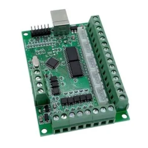
The hardware connections of a GRBL-based system are critically important for system stability and performance. Typically, an Arduino Uno and a CNC Shield V3 board mounted on it are used. Here are the main connection points and their explanations:
- Stepper Motor Connections (X, Y, Z, A): The CNC Shield has four stepper motor driver sockets (for X, Y, Z, and optionally A axes). A stepper motor driver (A4988, DRV8825, etc.) is plugged into each of these sockets for each axis. Ensure that the motor drivers are inserted in the correct orientation and that the correct microstepping jumpers are set, especially for drivers like DRV8825. Four-wire or six-wire cables for stepper motors like NEMA17 or NEMA23 are connected to each motor driver. It is important to ensure that the cables are connected in the correct phase sequence (usually A-A’, B-B’ or 1A-1B, 2A-2B). Incorrect connection will cause the motor not to rotate or to move erratically.
- Limit Switch Inputs (X+, Y+, Z+, E-Stop): The CNC Shield has pins for limit switches. They are usually labeled X+, Y+, Z+ and correspond to specific digital pins on the Arduino (e.g., D9, D10, D12). Limit switches, which indicate the end positions of each axis of the machine, are connected to these pins. In industrial applications, it is recommended to use Normally Closed (NC) contact switches and shielded cables to minimize electrical noise. The emergency stop (E-stop) button is also usually connected to a separate input (e.g., A5) and used to instantly stop all machine movement. It is safer to provide a hardware stop by controlling the ENABLE pins of the motor drivers or cutting the main power supply, rather than having the E-stop signal go directly to GRBL.
- Spindle Control: The CNC Shield typically uses two pins for spindle control: Spindle Enable (D13) and Spindle Direction (D12). Pin D11 is used for PWM (Pulse Width Modulation) signal for spindle speed control. These pins can be connected directly to a DC motor driver, a relay module (for AC spindles), or a VFD (Variable Frequency Drive) control board. When making connections, attention should be paid to the current requirements of the motor or relay used, and if necessary, isolation from the Arduino should be provided using an external driver or optocoupler.
- Probe Input (A5): GRBL supports a probe input to accurately find the zero point or surface on the workpiece. This input is usually connected to the Arduino’s A5 analog pin. The probe is typically a conductive plate or a special sensor that sends a signal to GRBL when it makes contact with the workpiece.
- Power Input: The CNC Shield has a separate power input (usually a DC jack or screw terminal). This input is used to power the stepper motors and drivers and typically provides a voltage between 12V and 36V DC. The Arduino Uno can be powered from this power source or a separate USB connection. It is essential to use a power supply with sufficient current capacity to meet the requirements of the motor drivers.
- External Driver Connections: For high-power stepper motors or more advanced drivers, the CNC Shield has external driver connection pins (Step, Dir, Enable). These pins are used to transmit signals from the Arduino to external, more powerful stepper motor drivers. These connections are usually made via optical isolators, providing electrical isolation between the Arduino and the external driver, which reduces noise and increases system safety.
Common Problems and Solutions
Common problems encountered in GRBL-based systems are usually due to electrical noise, incorrect configuration, or faulty wiring. Here are some frequently observed issues and suggested solutions:
- Motor Skipping Steps or Vibration: This problem typically arises from insufficient or excessive motor driver current, incorrect microstepping settings, mechanical binding, or the motor being unable to keep up with high speed and acceleration settings. As a solution, adjust the driver current to the motor’s nominal value, try increasing torque by lowering the microstepping setting, check for mechanical friction, and reduce the GRBL parameters $110, $111, $112 (maximum speed) and $120, $121, $122 (acceleration). Additionally, unshielded stepper motor cables or their proximity to control signals can cause electrical interference; isolate and shield the cables.
- Serial Port Communication Errors: Errors such as “Port could not be opened” or “device not found” are usually caused by incorrect COM port selection, missing or outdated USB serial converter drivers, or another software occupying the port. As a solution, check the correct COM port in Device Manager, select the correct port in Arduino IDE or G-code sender software, update USB drivers, and ensure no other application is using the port. Sometimes trying a different USB cable can also solve the problem.
- Limit Switch or E-stop Constantly Active: This situation typically results from incorrect limit switch wiring (NC instead of NO or vice versa), electrical noise, or incorrect logic in GRBL settings. As a solution, check the connection type of the switches (NC or NO) and configure the $5 (limit switch logic) setting in GRBL accordingly. Especially if NC switches are used, they offer a safer structure against cable breaks. Shield the cables and use ferrite beads to reduce electrical noise. Using a hardware interrupter for E-stop minimizes software-related issues.
- Axes Moving in Reverse: An axis moving in the opposite direction to what is expected is usually caused by incorrect stepper motor coil connections or an erroneous direction setting in GRBL. As a solution, try reversing the connections of one of the motor’s two coils (e.g., A-A’ or B-B’) or change the $3 (axis direction mask) parameter in GRBL to reverse the direction of the relevant axis. For example, if the X-axis moves in reverse, you can try $3=1 instead of $3=0 or vice versa.
- Spindle Control Issues (Not Turning On/Speed Not Adjustable): The spindle not operating at all or its speed not being controllable is usually due to incorrect wiring, insufficient power supply, or erroneous Spindle settings ($30, $31, $32) in GRBL. As a solution, ensure that the Spindle Enable, Direction, and PWM pins are correctly connected. If an external relay or motor driver is used, check that they are triggered correctly. Check the $30 (maximum spindle speed RPM) and $31 (minimum spindle speed RPM) values in GRBL; $32 (laser mode) should be set correctly if a laser is used. Ensure that the PWM frequency is compatible with the driver used.
Expert Advice
GRBL offers a powerful and practical solution for specific applications in industrial automation, particularly due to its cost-effectiveness and flexibility. This detailed field guide and technical article aimed to provide information across a wide range, from GRBL control board wiring diagrams to software installation processes, technical data analysis, and solutions for common problems. When integrating a GRBL system into an industrial environment, attention to detail is critically important for the system’s reliability and lifespan. It should be remembered that although it is an open-source platform, correct hardware selection, meticulous wiring, protection against electrical noise, and precise software calibration are essential for GRBL to operate at industrial standards. As expert advice, before starting the installation of any GRBL-based system, thoroughly analyze all project requirements and verify the compatibility and quality of the components to be used (stepper motors, drivers, power supplies, limit switches). Adhering to electrical safety standards, complying with grounding schemes, and designing emergency stop mechanisms as hardware play a vital role in preventing potential industrial accidents. Also, remember that GRBL has a continuously developing community, and current firmware versions may offer new features and improvements. Regularly checking for updates and upgrading your system to the latest stable version will be beneficial for performance and security. The flexible structure offered by GRBL opens up a wide field for engineers and technicians to develop their custom automation solutions, but utilizing this potential to its fullest requires in-depth technical knowledge and practical experience. We hope this guide will be a valuable resource for professionals in the industrial automation sector to more effectively set up, manage, and troubleshoot GRBL-based systems.
FAQ
What is GRBL and how does it function in industrial CNC applications?
GRBL is an open-source firmware designed for microcontrollers, primarily Arduino Uno, to interpret G-code commands for precise motion control in CNC machines, laser cutters, and 3D printers. It translates G-code into step and direction signals for stepper motors and manages peripherals like limit switches and spindle control.
What are the most important GRBL configuration settings for industrial CNC router machines?
Key parameters include the steps/mm ratio ($100, $101, $102) for each axis, maximum speed ($110, $111, $112), acceleration ($120, $121, $122), and limit switch logic ($23, $22). These settings are crucial for the machine's accuracy, speed, and safety, and are configured using '$' commands via a G-code sender software.
What are common troubleshooting steps for GRBL control board issues in an industrial setting?
Common issues include motor skipping steps (due to incorrect current, microstepping, or mechanical binding), serial communication errors (wrong COM port, outdated drivers), constant limit switch activation (faulty wiring, electrical noise), and axes moving in reverse (incorrect motor coil connections or GRBL direction settings). Solutions involve careful calibration, proper wiring, shielding, and correct GRBL parameter adjustments.
What are the best practices for wiring and power supply in a GRBL-controlled industrial CNC system?
For optimal performance, ensure stable and noise-free power supplies, use shielded cables for stepper motors and control signals, implement Normally Closed (NC) limit switches for safety, and design a hardware-based emergency stop. Proper cooling for drivers and motors, along with a clean operating environment, also extends component life and system reliability.
How do I install and configure GRBL firmware on an Arduino board for my industrial CNC router?
GRBL firmware is uploaded using the Arduino IDE. Download the GRBL source code, add it as a library in the IDE, open the 'grblUpload' example, connect your Arduino Uno, select the correct board and serial port, and click 'Upload'. After uploading, use a G-code sender software like Universal Gcode Sender (UGS) to configure the system parameters.



