
No products in the cart.
Design Tips for Heavy-Duty Linear Guide Systems
Contents
- Introduction and Technical Analysis of Design Tips for Heavy-Duty Linear Guide Systems
- Operating Principle and Technical Data for Heavy-Duty Linear Guide Systems
- Field Considerations for Heavy-Duty Linear Guide Systems Design Tips
- Common Problems and Solutions for Heavy-Duty Linear Guide Systems Design Tips
- Conclusion and Expert Advice on Heavy-Duty Linear Guide Systems Design Tips
- FAQ
Introduction and Technical Analysis of Design Tips for Heavy-Duty Linear Guide Systems
At the heart of industrial automation, **heavy-duty linear guide systems** are critical components that directly impact the efficiency and precision of manufacturing processes. In today’s competitive production environments, the expectation of high load capacity, excellent positioning accuracy, long lifespan, and uninterrupted operation makes the design and selection of these systems vital. Used in a wide range of applications from CNC machines to robotic systems, large-scale material handling systems, and precise assembly lines, heavy-duty linear guides must withstand dynamic and static loads, minimize vibration, and maintain stability even at high speeds. This technical article and field guide aim to provide comprehensive and practical information for industrial automation engineers, designers, and maintenance specialists on the correct selection, design, installation, and maintenance of heavy-duty linear guide systems. Our goal is to share fundamental principles and expert tips to help you find the optimal balance between **performance**, **reliability**, and **cost-effectiveness**.
Operating Principle and Technical Data for Heavy-Duty Linear Guide Systems
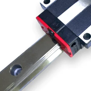
Heavy-duty linear guide systems are mechanical arrangements designed to provide precise and low-friction movement of a load along a predetermined linear path. They primarily consist of a **rail (guide)** on which one or more **guide blocks (carriages)** move, and **rolling elements** (ball, roller, or needle bearings) located between these two components. The load is distributed onto the rail via the guide blocks and moves with minimal friction thanks to the rolling elements. In heavy-duty applications, **roller** or **needle bearing** type guides are generally preferred, as they offer higher load capacity and better rigidity compared to ball guides due to their larger contact surfaces. The engineering data and operating principles of these systems are critically important in the design process:
- Dynamic Load Capacity (C): This is the maximum equivalent load a linear guide can continuously carry for a specified lifespan (typically 100 km or 50 million revolutions) at a certain reliability level (typically 90%). This value is fundamental for calculating applied dynamic loads (loads occurring during movement) and directly affects the guide’s lifespan.
- Static Load Capacity (C0): This is the maximum load the guide can withstand in a stationary state without permanent deformation or damage. It is particularly important for systems subject to loads at rest or sudden shock loads.
- Moment Load Capacities (Mx, My, Mz): These indicate the guide system’s resistance to moment loads along the pitch, yaw, and roll axes. Correct evaluation of these capacities is essential for the system’s rigidity and precision in applications with heavy and eccentric loads. Using multiple guide blocks and rails can help distribute moment loads.
- Service Life (L): The lifespan of linear guide systems is typically expressed in millions of revolutions or distance traveled. It is calculated using the formula: L = (C / P)^3 * 10^6 revolutions, where C is the dynamic load capacity and P is the equivalent dynamic load. In heavy-duty applications, correct sizing with safety factors must be applied to meet lifespan expectations. Insufficient sizing leads to premature wear and system failures.
- Rigidity (Stiffness): This indicates how much a guide deforms under an applied load. For heavy-duty and high-precision applications, guides with high rigidity should be preferred for minimum deflection. Roller-type guides generally offer higher rigidity than ball guides. Rigidity affects the system’s response time, vibration damping, and overall positioning accuracy.
- Friction Coefficient: This refers to the resistance generated during movement. A low friction coefficient means less energy consumption, lower heat generation, and a longer lifespan. Proper lubrication and precise surface finishing play a critical role in minimizing friction.
- Speed and Acceleration Limits: Each linear guide system has specific speed and acceleration limits depending on the characteristics of its rolling elements and lubrication. High speeds and accelerations under heavy loads can create excessive stress on guide elements and shorten their lifespan. Maximum speed and acceleration values in manufacturer catalogs must always be considered.
- Mounting Precision: The performance of linear guides is directly related to the flatness, parallelism, and accuracy of mounting torques of the mounting surfaces. Misalignment or mounting stresses can lead to uneven load distribution, premature wear, and vibration on the guide.
- Material and Surface Treatments: For heavy-duty applications, guide rails and blocks are typically made from high-strength, heat-treated steel. For environments requiring corrosion resistance, stainless steel or special coatings (hard chrome, black oxide, DLC, etc.) can be used. Surface hardness and roughness are critical for wear resistance and lifespan.
- Lubrication Systems: Proper lubrication is essential to reduce friction between rolling elements and rail surfaces, prevent wear, and dissipate heat. In heavy-duty and continuous operation conditions, automatic or centralized lubrication systems offer a more reliable and efficient solution than manual lubrication. The type (grease, oil) and viscosity of the lubricant should be selected according to operating temperature and load conditions.
| Parameter | Value/Description |
|---|---|
| Dynamic Load Capacity (C) | Typically 10 kN – 300 kN (varies by size and type) |
| Static Load Capacity (C0) | Typically 15 kN – 600 kN (can be 50-100% higher than C) |
| Maximum Speed | 1 m/s – 5 m/s (depending on application and lubrication) |
| Operating Temperature Range | -20°C to +80°C (can be extended with special lubricants and materials) |
| Material | High Carbon Chromium Steel (Heat Treated), Stainless Steel (for Corrosion Resistance) |
| Rigidity | High (especially in roller-type guides, deflection in μm/kN) |
| Life Calculation Formula | L = (C / P)^3 * 10^6 revolutions (or equivalent distance) |
| Lubrication Interval | 50 km – 500 km (varies by application, load, and environmental conditions) |
Field Considerations for Heavy-Duty Linear Guide Systems Design Tips
- Comprehensive Load Analysis and Load Distribution: One of the most significant factors affecting a system’s lifespan and performance is the accurate determination of the loads it will be subjected to. Analyze not only vertical loads but also horizontal, instantaneous shock, and especially **moment loads (bending, torsion, rotation)** in detail. Determine whether loads are applied centrally or eccentrically. For heavy and eccentric loads, distribute the load by using multiple guide blocks and rails to increase system rigidity and prevent excessive stress. Consider acceleration and deceleration forces when calculating dynamic loads. Size the system with appropriate safety factors for the loading conditions.
- Guide Selection Suitable for Environmental Conditions: The operating environment has a major impact on the lifespan and maintenance of the guide system. In dusty, humid, chemical vapor-exposed, or high/low-temperature environments, standard guides may be insufficient. For such conditions, prefer guides with reinforced **sealing elements (wipers, covers)**, made from **corrosion-resistant materials (stainless steel)**, or with special **surface coatings**. In environments with extreme temperature fluctuations, appropriate mounting methods and material compatibility should be considered to manage thermal expansion differences.
- Mounting Surface Preparation and Precise Alignment: The performance and lifespan of linear guide systems are directly proportional to the quality of their mounting surfaces. Mounting surfaces must be **flat, parallel, and smooth** according to manufacturer tolerances. Surface imperfections can cause stress between the guide blocks and rail, leading to premature wear, jamming, and loss of precision. During installation, ensure that the rails are **precisely aligned** with each other and with reference surfaces. Adhering to bolt torque values and using gradual tightening techniques prevents the formation of mounting stresses. Laser alignment tools or precise measurement equipment play a critical role in this stage.
- Correct Lubrication and Regular Maintenance Schedule: Lubrication is one of the most important maintenance requirements for linear guide systems. Insufficient or incorrect lubrication increases friction, generates heat, and leads to premature wear. The appropriate **grease or oil type** should be selected based on application conditions such as load, speed, temperature, and operating time. In heavy-duty and continuous operation conditions, using **automatic or centralized lubrication systems** in addition to manual lubrication provides consistent and effective lubrication, extending system life and reducing maintenance costs. The **periodic maintenance schedule** specified by the manufacturer must be strictly followed, and guides should be regularly cleaned and lubricated.
- System Rigidity and Vibration Damping: To achieve high precision under heavy loads, not only the rigidity of the guides but also the overall rigidity of the entire system (machine structure, guide supports, fasteners) is critically important. If the main structure to which the guides are mounted is not sufficiently rigid, it can flex under load, leading to loss of precision and vibration. In vibrating environments, vibration damping elements or more rigid guide configurations (e.g., wider rails or more guide blocks) can be used. Analyzing system resonance frequencies and keeping them away from operating frequencies helps minimize vibration problems.
- Thermal Management and Expansion Control: Thermal expansion is a significant factor, especially in heavy-duty systems operating with long strokes or in variable temperature environments. Temperature changes can cause dimensional changes in guide rails and machine structures, leading to stresses and alignment issues. To manage this, one end of the rails can be fixed while the other is left free, or special mounting methods that can absorb thermal expansion can be used. Additionally, appropriate lubrication and, if necessary, cooling measures should be considered to minimize and effectively dissipate friction-induced heat generation within the guide.
Common Problems and Solutions for Heavy-Duty Linear Guide Systems Design Tips
Problems encountered in heavy-duty linear guide systems typically arise from incorrect design, faulty installation, inadequate maintenance, or unsuitable environmental conditions. Early diagnosis and correct solutions extend system life and minimize downtime.
1. Premature Wear and Reduced Lifespan:
- Problem: Faster-than-expected wear, roughness, and loss of lifespan on guide surfaces or rolling elements.
- Causes:
- Overloading: Exceeding the specified dynamic or static load capacity.
- Insufficient Lubrication: Incorrect lubricant selection, long lubrication intervals, or lubrication system failure.
- Misalignment/Mounting Stress: Internal stresses caused by uneven mounting surfaces, non-parallel rails, or overtightened fasteners.
- Contaminated Environment: Entry of foreign particles such as dust, chips, moisture into the guide, causing abrasive effects.
- Vibration: Excessive vibration or resonance can cause fatigue on rolling elements.
- Solutions:
- Load Analysis and Resizing: Recalculate loads and resize guides by increasing safety factors. Use higher capacity or more guides if necessary.
- Lubrication Optimization: Select the correct lubricant (manufacturer recommendations), shorten lubrication intervals, and evaluate automatic lubrication systems. Ensure lubrication points are not clogged.
- Precise Mounting Control: Check the flatness and parallelism of mounting surfaces. Ensure rails are correctly aligned using laser alignment tools. Tighten mounting bolts to correct torque values and eliminate stress.
- Protective Elements: Protect guides from dirt and moisture using appropriate sealing elements, bellows, or telescopic covers suitable for the environment.
- Vibration Analysis: Identify system vibration sources and take damping measures.
2. Jamming, Difficulty in Movement, or Sticking:
- Problem: Guide block unable to move smoothly on the rail, sticking, or emitting high friction noise.
- Causes:
- Foreign Objects: Dirt, chips, metal particles entering the guide.
- Corrosion: Rusting on guide surfaces due to moisture or chemical exposure.
- Mounting Errors: Non-parallel rails, incorrect distance between rails, imperfections on the mounting surface.
- Damaged Rolling Elements: Damage to internal balls, rollers, or needle bearings.
- Thermal Expansion: Dimensional differences caused by extreme temperature changes.
- Solutions:
- Cleaning and Protection: Regularly clean guides and check the functionality of protective elements.
- Corrosion Prevention Measures: Use corrosion-resistant guides or apply appropriate protective lubricants/coatings.
- Realignment: Disassemble and re-mount guides precisely to correct mounting errors.
- Part Replacement: Replace damaged guide blocks or rails.
- Thermal Management: Control temperature changes or use mounting methods that allow for expansion.
3. Noise and Vibration:
- Problem: Abnormal sounds (squeaking, rattling) and vibrations during operation.
- Causes:
- Insufficient Lubrication: Dry or inadequately lubricated surfaces.
- Damaged Rolling Elements: Surface damage or irregularities on bearing elements.
- Mounting Errors: Loose connections, mounting surface imperfections, misalignment.
- Resonance: System natural frequency being close to the operating frequency.
- Overloading: Excessive stress on guide elements.
- Solutions:
- Lubrication Check: Check lubrication status and, if necessary, renew lubricant or optimize the system.
- Guide Inspection and Replacement: Inspect guide blocks and rails for signs of wear or damage. Replace damaged parts if necessary.
- Mounting Check: Check the tightness of all fasteners and correct alignment errors.
- Vibration Analysis and Damping: Determine system resonance frequencies and reduce vibration by adding damping elements or changing operating speeds.
- Load Reduction: If possible, reduce the load on the system or replace guides with higher capacity models.
4. Loss of Precision and Positioning Errors:
- Problem: System unable to achieve desired positioning accuracy or repeatability.
- Causes:
- Wear: Wear on guide surfaces or rolling elements creates backlash.
- Deformation: Permanent deformation in guide elements or support structure due to excessive load or thermal expansion.
- Loose Connections: Loosening of mounting bolts for guide blocks or rails.
- Control System Issues: Errors in feedback systems or drives (systemic effect, even if not directly related to the guide).
- Solutions:
- Regular Inspection and Maintenance: Conduct regular checks to detect signs of wear early.
- Part Replacement: Replace worn or deformed guide elements.
- Tightness of Fasteners: Check all mounting bolts and tighten with the correct torque.
- Control System Diagnosis: Check the control system and sensors.
- Increase Rigidity: If necessary, increase the overall rigidity of the system by using more rigid guides or support structures.
Conclusion and Expert Advice on Heavy-Duty Linear Guide Systems Design Tips
In the modern dynamics of industrial automation, heavy-duty linear guide systems form the backbone of production processes, needing to meet expectations of precision, speed, and durability. The details covered in this comprehensive field guide clearly demonstrate that a linear guide system is more than just a component; it requires a holistic engineering approach. Correct design, meticulous product selection, flawless installation, and continuous maintenance are indispensable elements that directly affect the lifespan, performance, and thus the overall efficiency of your operations. It should be remembered that the operating and maintenance costs incurred over a system’s lifecycle are as important as its initial cost. Correct engineering choices made at the outset lead to significant savings in the long run by preventing unexpected failures, production downtimes, and high repair costs. Especially in heavy-duty applications, neglecting critical parameters such as load capacity, rigidity, expected lifespan, environmental conditions, and lubrication can lead to premature aging of the system and unexpected performance losses. Therefore, in-depth analysis of each project’s unique requirements, meticulous examination of manufacturer technical data, and seeking expert engineering support when necessary are of vital importance. At the heart of your heavy-duty linear guide systems lie correct engineering, proper product selection, and meticulous installation; adhering to these principles will establish a solid foundation for achieving your industrial automation goals. A high-performance and smoothly operating system is not just an immediate success, but also a guarantee of your future production capacity and competitive strength.
FAQ
What are heavy-duty linear guide systems and how do they work?
Heavy-duty linear guide systems are mechanical assemblies designed to provide precise, low-friction linear motion for heavy loads. They consist of a rail (guide), one or more guide blocks (carriages), and rolling elements (balls, rollers, or needle bearings) that facilitate smooth movement. These systems are crucial for industrial automation, ensuring high load capacity, positioning accuracy, and durability in demanding applications.
What technical parameters are most important when selecting heavy-duty linear guides?
Key technical parameters include Dynamic Load Capacity (C) for continuous operation, Static Load Capacity (C0) for stationary loads, Moment Load Capacities (Mx, My, Mz) for resistance to bending/twisting, Service Life (L) calculated based on load, Rigidity (Stiffness) for minimal deformation, Friction Coefficient for energy efficiency, and Speed/Acceleration Limits. Material selection, surface treatments, and lubrication systems are also critical for performance and longevity.
How can I ensure the longevity and optimal performance of my heavy-duty linear guide system?
Proper lubrication is paramount. Use the correct type of grease or oil recommended by the manufacturer, establish regular lubrication intervals, and consider automatic lubrication systems for continuous operation. Additionally, ensure mounting surfaces are flat and parallel, protect guides from contaminants with seals and covers, and conduct periodic inspections for wear and damage. Adhering to manufacturer maintenance schedules is essential.
What are the most common problems encountered with heavy-duty linear guide systems and how can they be resolved?
Common issues include premature wear (due to overloading, poor lubrication, or misalignment), jamming/sticking (from foreign objects, corrosion, or mounting errors), noise/vibration (from inadequate lubrication, damaged components, or resonance), and loss of precision (due to wear, deformation, or loose connections). Each problem requires a specific diagnostic approach and corrective action, often involving load recalculation, lubrication optimization, or precise re-alignment.
What are the critical design considerations for integrating heavy-duty linear guides into an industrial machine?
When designing with heavy-duty linear guides, conduct a comprehensive load analysis, including static, dynamic, and moment loads. Select guides suitable for the environmental conditions (e.g., corrosion-resistant for humid environments). Ensure precise mounting surface preparation and alignment. Implement a robust lubrication program and consider the overall system rigidity and thermal management to prevent issues from thermal expansion.



