



































































































































Control Panel Rail Type Terminal Block Layout and Cable Labeling System

📑 Table of contents (Click to open)
Introduction and Technical Analysis
Control panels, the heart of industrial automation systems, play a critical role in the smooth and efficient operation of modern manufacturing facilities. Within these panels, the rail-type terminal block layout and cable labeling system directly impact system reliability, ease of maintenance, troubleshooting speed, and overall operational safety. Advanced automation systems can involve hundreds or even thousands of cable connections. Managing this complex structure effectively is more than just an aesthetic arrangement; it’s a strategic approach combining engineering discipline and field experience. An incorrect or incomplete layout can lead to wasted time, production downtime, safety risks, and even equipment damage. This guide aims to provide a roadmap for optimum performance and sustainability by thoroughly examining the standards, technical details, and field applications of control panel terminal block layout and cable labeling for industrial automation professionals.
Operating Principle and Technical Data
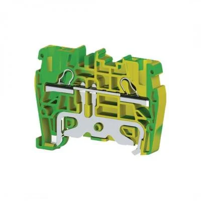
Rail-type terminal blocks are modular electrical connection components that can be easily mounted on DIN rails. This modular structure offers flexibility and expansion capabilities according to the panel’s needs. They are primarily used to safely and neatly transfer electrical signals or power supplies from one cable end to another. Various types are available: pass-through terminals (feed-through terminals), grounding terminals, fuse terminals, disconnect terminals, sensor/actuator terminals, and multi-level terminals. Each type serves a specific function, reducing wiring complexity within the panel and creating a clear structure.
Key technical data to consider when selecting terminal blocks are closely related to the system’s electrical requirements. Rated current and rated voltage values indicate the maximum current and voltage the terminal block can handle and must be compatible with the system’s power requirements. The cable cross-section should be selected according to the thickness of the cable to be connected; a wide range is typically offered, from 0.2 mm² to 95 mm². Connection technologies are divided into three main types: screw connection, spring clamp connection (spring terminal), and push-in connection. Screw connections provide a strong mechanical grip, while spring clamp and push-in connections offer practical, tool-free solutions that are faster and more resistant to vibration. Spring clamp and push-in types should be preferred, especially in applications with high vibration or requiring quick connections.
In control panel layouts, grouping terminals by function is of great importance. For example, 24V DC control signals, 230V AC power lines, safety circuit signals, and communication lines (Profinet, EtherCAT, etc.) should be separated on different DIN rails or clearly demarcated with distinct gaps on the same rail. This segregation principle minimizes electromagnetic compatibility (EMC) issues, simplifies fault finding, and enhances safety by preventing accidental energization during maintenance. Grounding terminals, always green/yellow, must provide a safe ground connection to the panel chassis by directly contacting the DIN rail. At the beginning and end of terminal block rows, a terminal end stop and a label holder are typically used to reinforce the clarity of the layout.
Cable labeling is the fundamental element that makes the panel “speak.” Labeling standardization should be carried out within the framework of international standards such as IEC 81346 or specific in-house standards. Each cable end must be equipped with a clear and legible label, explicitly indicating which terminal the cable is connected to, which circuit it represents, and/or which component it leads to. Labels must be made of durable material resistant to heat, moisture, oil, and UV radiation. Laser-printed labels or heat-shrinkable sleeve labels are the most frequently preferred and durable solutions in industrial environments. Label information typically consists of a combination of a project number, page number, line number, and terminal number. This detailed labeling must be in full compliance with circuit diagrams, enabling field personnel to intervene quickly and error-free.
| Parameter | Value/Description |
|---|---|
| Terminal Type | Pass-through, Grounding, Fuse, Disconnect, Multi-level |
| Connection Technology | Screw, Spring Clamp (Spring-Cage), Push-in |
| Rated Current Range | 0.1 A – 200 A (Varies by model and cross-section) |
| Rated Voltage Range | 24 V DC – 1000 V AC/DC (Varies by model) |
| Cable Cross-Section Range | 0.2 mm² – 95 mm² (AWG 24 – AWG 0000) |
| Insulation Material | Polyamide (PA), Melamine – Halogen-free |
| Operating Temperature | -40°C to +105°C (Verify with manufacturer datasheet) |
Field Considerations
- Standardization and Project Documentation Compliance: At the start of every project, specific standards (in-house or international) for terminal block layout and labeling must be defined and strictly adhered to. All project documentation, such as terminal lists, cable connection diagrams, and panel layout plans, must precisely match the actual field application. Any deviation can lead to serious issues during maintenance and troubleshooting. The labeling format and content must be fully consistent with the reference points in the project schematics, ensuring no hesitation when tracing a cable.
- Ergonomics, Accessibility, and Expansion Space: When designing the terminal block layout, future expansion possibilities, maintenance, and troubleshooting operations must be considered. Sufficient space should be left between each terminal group or at specific intervals for new cable connections. Additionally, adequate working space must be provided for measurement tools like test probes or multimeters to easily access the terminals. Cable ducts and rails should be positioned to allow for neat routing of cables and clean access to the terminals. In particular, the accessibility and replaceability of cables located behind the terminal blocks are critical.
- EMC Compliance and Signal Integrity: Electromagnetic interference is a common problem in industrial environments. Therefore, EMC (Electromagnetic Compatibility) principles must be meticulously applied in the terminal block layout. Power cables, control signal cables, and communication cables must be physically separated. Sensitive analog signals and high-speed communication cables should be protected by using shielded cables and keeping them sufficiently distant from other power lines in the terminal block layout. Grounding terminals and shield connections should be made from a single point or via appropriate grounding bars, in accordance with the star grounding principle, to prevent the formation of ground loops.
- Cable Routing and Securing: The routing of cables before they reach the terminals is vital for the overall organization and longevity of the panel. Cables should be routed avoiding sharp bends, adhering to appropriate bend radii, and neatly secured using cable ducts or cable ties. Sufficient slack and strain relief mechanisms should be provided at the terminal entries to prevent cable tension. Furthermore, the use of correct cable stripping lengths and ferrules is mandatory to prevent excessive compression of cables at terminal entries and reduce the risk of mechanical damage. All these practices minimize cable insulation wear over time and the risk of short circuits.
- Label Material and Readability: The durability and readability of labels are critical throughout the lifespan of the panel. Label materials resistant to temperature fluctuations, humidity, dust, oil, and chemicals that industrial panels may be exposed to must be selected. Laser-printed labels, thermal transfer printed labels, or heat-shrinkable sleeve labels are generally the most durable and long-lasting solutions. The label font size and style should be easily readable, considering the panel’s mounting height and lighting conditions. Quality adhesives or permanent fixing methods should be used to ensure labels do not fade or detach over time. Double-sided labeling, indicating both source and destination information on each cable end, saves time during fault situations.
Common Problems and Solutions
Problems encountered in field terminal block layout and cable labeling often stem from factors such as carelessness, lack of knowledge, or cost pressures. One of the most common issues is loose connections. Due to vibration, thermal expansion/contraction, or insufficient tightening torque, connections in screw terminals can loosen over time. This leads to increased contact resistance, overheating, signal loss, or complete connection failure. As a solution, it is essential to use a torque wrench for screw terminals, tightening to the torque values specified by the manufacturer, and to periodically check connections. Spring clamp or push-in terminals are inherently more resistant to such loosening issues and should be preferred in vibrating environments.
Another common problem is incorrect or missing wiring and labeling. Especially in intensive projects or under time constraints, cables being connected to the wrong terminals or labels being missing or erroneous are frequently observed. This can cause delays in system commissioning, malfunctions, and even serious safety risks. The solution involves using detailed and up-to-date project schematics, performing quality checks after every connection, and providing adequate training to the wiring team. Additionally, using ferrules for cable ends prevents fraying and ensures reliable contact.
Insufficient internal panel space management poses a significant obstacle to terminal block layout and cable routing. Failure to leave adequate space initially or not anticipating future expansions can lead to the panel becoming complex and difficult to maintain over time. This can cause cables to bend excessively, make access to terminals difficult, and obstruct airflow. The solution is to allocate sufficient space for terminal block layout and cable ducts through detailed 3D CAD modeling during the panel design phase. Furthermore, using space-saving solutions like multi-level terminals and planning modular expansion strategies are important.
Labels becoming unreadable or detaching is a problem encountered, especially in harsh industrial environments. Low-quality label materials or incorrect printing methods can cause labels to fade, wear off, or lose their adhesive properties over time. This makes it impossible to identify the correct cable during maintenance and extends troubleshooting time. The solution, as mentioned above, is to use high-quality label materials (laser-printed, thermal transfer, or heat-shrinkable sleeves) that are resistant to heat, moisture, oil, and chemicals. Ensure that labels adhere firmly to the cable and will not detach easily. Double-sided labeling or applying multiple labels on the cable reduces these risks.
Expert Advice
The effectiveness of control panels, the core of industrial automation systems, largely depends on the quality of the internal rail-type terminal block layout and cable labeling system. While these details may seem simple at first glance, they are critical engineering decisions that profoundly affect the system’s reliability, ease of maintenance, and operational efficiency throughout its lifecycle. My experience as an expert field engineer shows that a well-planned and meticulously implemented terminal block and labeling strategy provides numerous benefits not only during the installation phase but also throughout the system’s entire lifecycle. Adherence to standards, ergonomic design, EMC compliance, and durable labeling reduce production downtime in the long run, shorten fault finding times, minimize safety risks, and most importantly, ensure that field personnel can work safely and efficiently. Adhering to the principles outlined in this guide will not only solve current problems in your industrial automation projects but also create a solid foundation for potential future challenges. Remember, the internal organization of a control panel is a reflection of the professionalism of the team that designs and installs it. Attention to detail is the key to operational excellence.


