
No products in the cart.
Chassis Construction with Sigma Profiles: Robustness and Flexibility Tips
Contents
Chassis Construction with Sigma Profiles: Robustness and Flexibility Tips (Field Guide and Technical Article)


Introduction and Technical Analysis
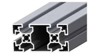
In today’s rapidly evolving world of industrial automation, the design and construction of chassis, which form the foundation of machines and systems, are of critical importance. Modular aluminum profile systems, especially Sigma Profiles, have revolutionized the industry, replacing traditional welded steel constructions. These profiles are structural elements produced by extrusion from high-strength aluminum alloys, typically featuring T-slot channels. They are widely used in industrial automation applications such as robotic cells, conveyor systems, test stands, machine frames, protective enclosures, and ergonomic workstations. The advantages offered by Sigma profiles, including modularity, flexibility, rapid assembly, and ease of disassembly, are indispensable for optimizing production processes and reducing investment costs. Compared to traditional methods, they significantly shorten assembly times by eliminating the need for welding, easily adapt to design changes, and allow for system reconfiguration. This provides engineers and technicians with unique adaptability at every stage, from prototyping to mass production. Furthermore, the lightweight nature of aluminum reduces the overall weight of the chassis, while anodized coating ensures high corrosion resistance and an aesthetic appearance. This guide provides an expert perspective on the technical details of chassis construction with Sigma profiles, critical points in field applications, and practical solutions to potential problems.
Operating Principle and Technical Data
The operating principle of Sigma profiles revolves around standardized T-slot channels and compatible connection elements. Profiles are produced in various cross-sectional dimensions (e.g., 20×20, 30×30, 40×40, 45×45, 60×60, 80×80 mm) and different wall thicknesses, allowing for the creation of structures with varying load-bearing capacities. They are typically manufactured from aluminum alloys such as EN AW-6063-T5 or EN AW-6060-T6, and their surfaces are usually protected with an anodized coating. This coating thickens the natural oxidation layer of aluminum, increasing its corrosion resistance and providing protection against external effects such as scratches and abrasion. Key connection elements used in chassis construction include T-nuts (hammer head, spring-loaded, block type), bolts (M6, M8, M10), corner connectors (internal connection sets, external corner brackets, angular connections), and profile connectors. T-nuts are inserted into the T-slot channels of the profiles and used to secure other profiles or accessories via bolts. This system offers fast and secure assembly without any welding. During the design process, the correct selection of profile cross-section and connection elements is critical, considering the loads the chassis will bear (static, dynamic, vibrational), the application environment, aesthetic expectations, and cost factors. Engineering calculations are performed, especially on parameters such as bending moment, torsional strength, and vibration analysis. CAD software is widely used to ensure design accuracy and optimization. Additionally, various accessories such as integrated channels for cable management, slots for panels, and adjustable feet enhance the functionality of Sigma profile systems.
| Parameter | Value/Description |
|---|---|
| Material | EN AW-6063 T5 / EN AW-6060 T6 Aluminum Alloy |
| Surface Treatment | Anodized Coating, 10-15 µm Thickness |
| Standard Profile Cross-sections | 20×20, 30×30, 40×40, 45×45, 60×60, 80×80 mm (Common) |
| T-Slot Width | 6mm, 8mm, 10mm (Varies by Profile Series) |
| Tensile Strength (Rm) | 190-220 MPa (Varies by Alloy and Treatment) |
| Modulus of Elasticity (E) | 69 GPa |
| Specific Gravity | Approximately 2.7 g/cm³ |
| Connection Element Types | T-nuts (M6, M8), Corner Brackets, Internal Connection Sets |
| Maximum Connection Torque | Must be checked according to manufacturer datasheet value. |
| Cutting Tolerance | ±0.2 mm (Industrial Standard) |
Field Considerations
- Correct Profile and Connection Element Selection: The appropriate profile cross-section and connection element type must be selected considering the magnitude of the load the chassis will bear, dynamic effects (vibration, impact), and environmental conditions (humidity, chemicals). For heavy loads or high-vibration applications, larger cross-section profiles and reinforced connection elements (e.g., internal connection sets or strong angular connections instead of cast corner brackets) should be preferred. Incorrect selection can lead to chassis deformation or loss of stability over time.
- Cutting and Machining Precision: The cutting angles and lengths of the profiles must be extremely precise. Even small deviations in 90-degree cuts can lead to gaps during assembly and consequently reduce the overall strength of the chassis. Burrs can block T-slot channels or prevent connection elements from seating properly, so deburring after cutting must be done meticulously. Using precision cutting machines and measuring tools is critical at this stage.
- Correct Application of Connection Elements and Torque Values: Each connection element must be tightened according to the manufacturer’s specified torque values. Overtightening can damage profiles or connection elements, while undertightening can cause the connection to loosen and the chassis to lose stability. Using torque wrenches to adhere to these values ensures long-lasting and reliable connections. Additionally, using extra security elements like lock washers or spring washers in vibrating environments can be beneficial.
- Vibration Control and Damping: Vibration is inevitable in industrial automation environments. To minimize the effects of vibration in chassis design, additional supports, cross-bracing, or vibration-damping feet and intermediate elements should be used. Regular inspection of connection points and retorquing loose bolts can prevent vibration-related problems. In areas with intense vibration, more rigid solutions for profile and connection element selection should be pursued.
- Electrical Conductivity and Grounding: The anodized coating of aluminum profiles forms an electrically insulating layer. This can lead to grounding issues, especially in chassis where electrical panels or sensitive electronic equipment are mounted. For electrical safety and EMC (Electromagnetic Compatibility) requirements, it is essential to ground the chassis at appropriate points and ensure electrical continuity of all parts using conductive connection elements (e.g., special grounding sets or contact points where the coating has been removed).
- Assembly Sequence and Ergonomics: A correct sequence must be followed for the assembly of large and complex chassis. Typically, the main frame is erected first, followed by support elements and accessories. The design should consider accessibility, ease of maintenance, and future modifications during assembly. A clean and organized work area minimizes assembly errors and increases efficiency. Appropriate lifting equipment should be used for lifting and positioning heavy parts.
- Corrosion Prevention and Environmental Effects: While anodized coating protects aluminum against corrosion in most environments, additional measures may be required in special environments with aggressive chemicals or salt spray. Stainless steel connection elements or special protective coatings can extend the life of the chassis in such situations. Environmental factors such as ambient temperature and humidity should also be considered in material selection and design.
Common Problems and Solutions
In chassis construction with Sigma profiles, various problems can be encountered during the design and application phases. Knowing these problems beforehand and understanding their solutions is critical for project success.
- Chassis Flexing or Deformation:
Problem: The chassis exhibits flexing, twisting, or permanent deformation under load. This usually results from insufficient profile cross-section selection, weak connection points, or inadequate cross-bracing. This problem becomes more pronounced with dynamic loads or high-vibration applications.
Solution: Load calculations must be meticulously performed during the design phase, and necessary safety factors applied. Strength can be increased by preferring profiles with larger cross-sections or thicker walls. Weak connection points should be reinforced with stronger connection elements (e.g., internal connection sets or cast corner brackets). Additional cross-bracing, gussets, or truss structures should be added to increase chassis rigidity. Especially for long spans, increasing support points also helps reduce flexing.
- Loosening of Connection Elements:
Problem: Over time or due to continuous vibration, bolts loosen, causing the chassis to lose stability and even parts to separate. Incorrect torquing, inappropriate connection element selection, or inadequate vibration control trigger this problem.
Solution: Connection elements should always be tightened with a torque wrench according to the manufacturer’s recommended torque values. In vibrating environments, spring washers, lock washers, lock nuts, or liquid threadlockers (like Loctite) should be used to prevent bolts from loosening. During regular maintenance checks, the torque values of all connection points should be verified and retightened if necessary. Placing rubber gaskets or vibration-damping pads between profiles can also reduce vibration transmission and prevent loosening.
- Assembly Difficulties and Incompatibilities:
Problem: Incompatibilities encountered during assembly, such as profiles not fitting together perfectly, T-nuts jamming when entering channels, or connection elements not aligning properly. This is usually related to imprecise cuts, burrs, or using the wrong type of T-nut.
Solution: Ensure that profile cuts are absolutely precise and angled correctly (typically 90 degrees). All burrs must be carefully removed after cutting; otherwise, T-nuts may not enter the channel or may jam. Ensure that the T-nuts used are compatible with the T-slot channel width and depth of the profile (e.g., 8mm T-nut for an 8mm slot). Using assembly jigs or special clamps to fix and align profiles during assembly can facilitate the process. If necessary, special guided T-nuts can be preferred for easy insertion into the channel.
- Electrical Conductivity Issues:
Problem: Due to the electrically insulating nature of anodized aluminum profiles, the chassis may not provide adequate grounding or sufficient electrical continuity for equipment such as electrical panels.
Solution: Special grounding sets or conductive connection plates should be used to ensure electrical continuity of each section of the chassis and all metal components. These elements penetrate the anodized layer to provide metal-to-metal contact, creating a safe grounding path. It is mandatory to connect the chassis to the main grounding line with a cable of appropriate cross-section. Especially in systems with sensitive electronic equipment, grounding and shielding methods compliant with EMC requirements must be applied.
- Corrosion and Surface Damage:
Problem: Damage to the anodized coating and corrosion of aluminum in conditions such as aggressive chemical environments, high humidity, or salt spray. Also, scratches on the surface due to mechanical impacts or abrasion.
Solution: The chassis should be designed with materials suitable for the chemical and physical conditions of the operating environment. Thicker anodized coatings or special powder-coated profiles can be preferred for abrasive environments. Using stainless steel (e.g., A2 or A4 grades) for connection elements increases corrosion resistance. Protective covers or bumpers can be used for chassis surfaces exposed to external effects. Regular cleaning and application of surface protective products can also extend the lifespan.
Expert Advice
Chassis construction with Sigma profiles has become an indispensable solution for engineers and technicians in the industrial automation sector seeking efficiency, flexibility, and cost-effectiveness. Its modular structure accelerates design and assembly processes, while its ability to easily adapt to future changes increases the long-term value of the investment. However, to fully benefit from these advantages, meticulousness and technical knowledge are required at every step, from design to assembly and even maintenance. Critical points such as correct profile and connection element selection, precise cutting and assembly techniques, adherence to torque values, vibration control, and electrical safety directly affect the chassis’s robustness, longevity, and operational reliability. Based on my field experience, I can confidently say that detailed preliminary engineering work and quality material selection prevent a large portion of potential problems from arising, even in the most complex projects. Especially in applications requiring dynamic loads or high precision, utilizing simulation software and allocating sufficient time for the prototyping phase ensures that the final product meets expectations. Supplier selection also plays a significant role in this process; quality profiles and accessories obtained from a reliable supplier directly contribute to the overall performance of the system. It should be remembered that Sigma profiles are not just structural elements but also tools that add flexibility to engineering solutions. By correctly using these tools, you can ensure that your industrial automation systems are both robust and future-proof. Continuous learning, following new connection technologies, and incorporating field feedback into designs will strengthen your expertise in this area and increase your competitive edge in the industry.
FAQ
What are Sigma profiles and what are their main benefits in industrial applications?
Sigma profiles are modular aluminum structural elements with T-slot channels, used to build robust and flexible frames for industrial automation. They allow for rapid assembly without welding, easy modification, and high adaptability.
How do I choose the right Sigma profile and connection elements for my chassis?
Key factors include the magnitude and type of load (static, dynamic, vibrational), environmental conditions (humidity, chemicals), and required aesthetic. Selecting the correct profile cross-section, wall thickness, and reinforced connection elements is crucial for stability and longevity.
What are the critical assembly tips for building a chassis with Sigma profiles?
Precision in cutting and deburring is paramount. Small deviations can cause gaps and reduce structural integrity. Always use a torque wrench to tighten connection elements to manufacturer-specified values to prevent loosening and ensure long-term reliability.
How should electrical grounding be handled when using anodized Sigma profiles?
Anodized aluminum profiles are electrically insulating. For safety and EMC compliance, ensure proper grounding using special grounding sets or conductive connection plates that penetrate the anodized layer. Connect the chassis to the main grounding line with an appropriate cable.
What are common problems encountered during Sigma profile chassis construction and how can they be resolved?
Common issues include chassis flexing (due to undersized profiles), loosening connections (due to vibration or improper torquing), and assembly incompatibilities (due to imprecise cuts or burrs). Solutions involve careful design, correct torque application, and using vibration-damping elements.



