



































































































































Calculating Cable Density When Selecting Flexible Cable Carriers

📑 Table of contents (Click to open)
Introduction and Technical Analysis
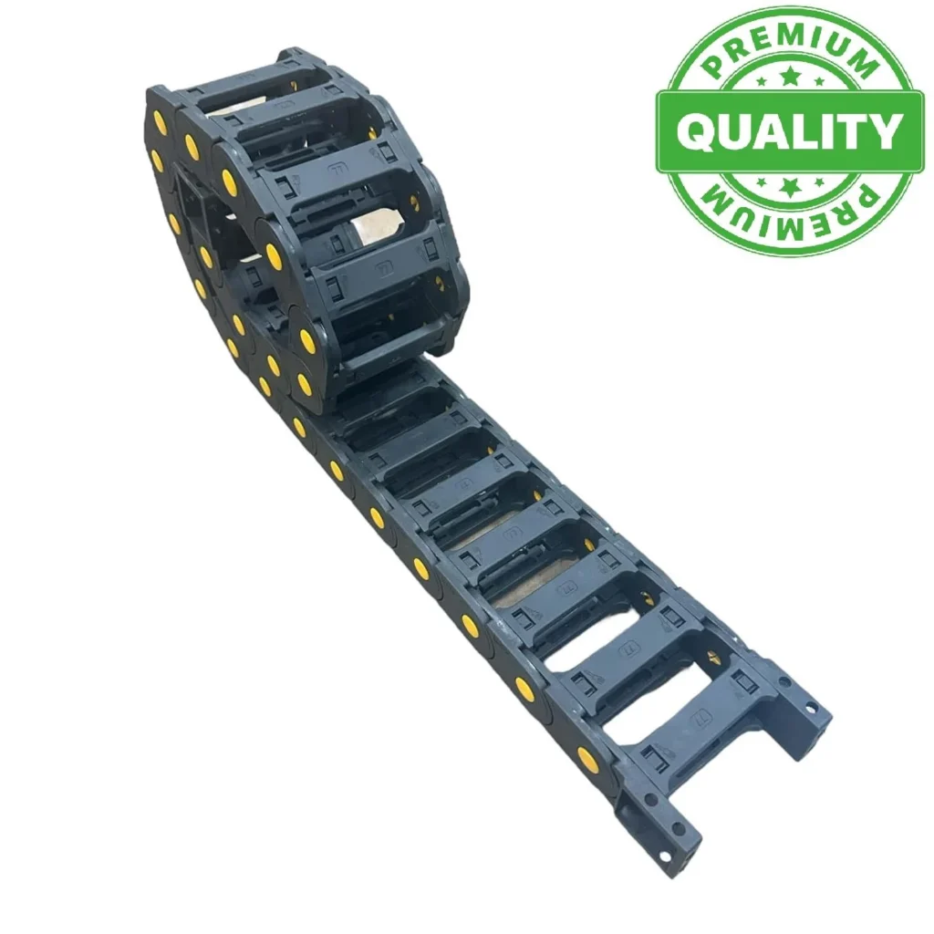
In the heart of industrial automation systems, particularly in moving applications, the safe, organized, and long-lasting management of cables that transmit electrical signals and power is critically important. Flexible cable carriers, also known as energy chains or cable tracks, are indispensable components of modern production lines, robotic systems, and CNC machines. However, it is a significant misconception to think of these channels as mere carriers. The correct selection of an energy chain directly impacts the system’s overall performance, uptime, and maintenance costs. This article will thoroughly explain to engineers, technicians, and system integrators in the industrial automation sector why calculating cable density is so crucial when selecting flexible cable carriers and how this process should be managed correctly.
Cable density calculation is the process of determining the ratio of an energy chain’s internal volume to the total volume of cables and hoses to be placed inside it. This calculation not only checks if the cables physically fit into the channel but also ensures the long-term reliability of the system by preventing cables from rubbing against each other, exceeding bending radius limits, and overheating. Incorrect cable density calculation can lead to premature cable wear, signal degradation, mechanical failures, and even complete system shutdown. These situations can result in unexpected production losses, high repair costs, and damage to brand reputation. Therefore, the care taken in this engineering process is a fundamental step for the success of automation projects.
Operating Principle and Technical Data
Flexible cable carriers are mechanical systems designed to safely route, protect, and maintain the bending radii of cables and hoses in moving machinery. The basic operating principle is that a chain composed of interconnected links flexes with the machine’s movement, keeping the cables within a specified bending radius. This prevents excessive bending of the cables, which could lead to breakage of internal conductors or damage to insulation. Cable density calculation is a critical step for maintaining this operating principle efficiently and safely.

Fundamentals of Cable Density Calculation
The main factors to consider in cable density calculation are:
- Number and Diameters of Cables: The outer diameter (OD) in millimeters of each cable (power, signal, data, fiber optic) and hose (pneumatic, hydraulic) to be placed inside must be accurately determined. This is the most basic and important data.
- Cable Type and Characteristics: Cable flexibility, bending radius requirements (typically 7 to 20 times the cable diameter), weight, and outer sheath material (PVC, PUR, TPE) can vary. Cables requiring high flexibility (e.g., robotic cables, servo cables) may need a larger bending radius, which affects channel selection.
- Filling Factor: This is the ratio indicating how much of the usable internal volume of the energy chain will be filled by cables. A filling factor of 60% to 70% is generally recommended. This ensures that cables move freely, prevents them from rubbing against each other, and optimizes heat dissipation. A 100% filling factor will lead to cable compression, overheating, and premature failure.
- Separators and Dividers: It is important to separate different types of cables (e.g., power cables from signal/data cables) to prevent electromagnetic compatibility (EMC) issues and reduce mechanical wear. Vertical and horizontal separators are used to create different compartments within the energy chain. These separators also occupy part of the internal volume and must be included in the calculation.
- Bending Radius (R): The minimum bending radius of the energy chain must not be smaller than the bending radius requirement of the most critical cable inside it. This factor directly affects the cable’s lifespan. An incorrect bending radius can cause permanent damage to the cable’s internal structure.
- Application Dynamics: Movement speed, acceleration, travel distance, and cycle count determine the stress on the cables and the chain. High-speed and high-acceleration applications require a more robust and optimized cable arrangement.
- Environmental Conditions: Factors such as operating temperature, humidity, dust, chemical exposure, or UV radiation affect the material of both the cables and the energy chain, thus changing the selection criteria.
Calculation Method
For a simple cable density calculation, the following steps can be followed:
- Calculate the Area of Each Cable: Calculate the cross-sectional area (A) of each cable using its outer diameter (D): A = π * (D/2)².
- Calculate Total Cable Area: Sum the cross-sectional areas of all cables to find the total cable area (A_total).
- Determine Energy Chain Internal Area: Calculate the internal area (A_chain) of the selected energy chain by multiplying its usable internal width (W_i) and internal height (H_i): A_chain = W_i * H_i.
- Check Filling Factor: Check if the ratio (A_total / A_chain) is within the recommended filling factor range (60-70%). This ratio indicates whether sufficient space is left for the cables to be comfortably placed. However, this is a simplified approach, and more sophisticated calculations are needed due to the circular nature of cables and the presence of separators.
In real-world applications, simple area calculations can be misleading due to the circular nature of cables and how they are arranged within the chain. Therefore, using specialized configuration tools and software provided by energy chain manufacturers yields much more accurate results for simulating the optimal placement of cables and separators. These tools automatically determine the recommended chain size and required separator configuration when cable diameters, numbers, and types are entered.
| Parameter | Value/Description |
|---|---|
| Recommended Filling Factor | 60% – 70% (Maximum 80%, except for special cases) |
| Cable Bending Radius (R) | 7-20 times cable diameter (Must be checked against manufacturer’s datasheet) |
| Maximum Travel Speed | Up to 10 m/s (Varies by application and chain type) |
| Maximum Acceleration | Up to 50 m/s² (Varies by application and chain type) |
| Operating Temperature Range | -40°C to +130°C (Varies by material, PA, PP, special alloys) |
| Internal Width Tolerance | ±0.5 mm (Varies by manufacturer and model) |
| Maximum Cable Weight (Supported Application) | Up to 50 kg/m (Varies by chain size and carrying capacity) |
| Material | Polyamide (PA), Polypropylene (PP), Steel, Hybrid (Selected according to application conditions) |
Field Considerations
- Correct Bending Radius Selection: Each cable has its own minimum bending radius. The bending radius (R) of the energy chain must not be smaller than the minimum bending radius of any cable inside it. Otherwise, the cable’s conductors will be stressed, insulation will be damaged, and cable life will be significantly shortened. This is critically important for data and fiber optic cables.
- Cable Separation and Arrangement: Power, signal, data, and fiber optic cables must be separated within the energy chain using appropriate dividers. This separation prevents electromagnetic interference (EMI) and reduces mechanical wear by preventing cables from rubbing against each other. Heavy cables should generally be placed near the outer edges of the chain, while light and sensitive cables should be placed closer to the center.
- Weight Distribution and Balance: The weight of the cables should be distributed as evenly as possible within the energy chain. Uneven load distribution can lead to one-sided wear, twisting, and premature failure of the chain. Especially over long travel distances, weight distribution becomes even more critical.
- Allowance for Future Expansion: Future potential needs should always be considered in system design. An energy chain filled to full capacity at the outset will cause problems if additional cables or hoses are needed later. Therefore, a 60-70% filling factor also provides some room for future expansions.
- Mounting and Fixing Points: It is essential that cables are secured (strain relief) at both ends of the energy chain without tension. Cable clamps or special holders should be used. Cables should be allowed to move freely within the chain, but excessive tension should not occur at the fixing points. Incorrect fixation can lead to cable breakage at connection points or cause a “handrail” effect within the chain, preventing it from operating smoothly.
- Environmental Protection: Industrial environments can often be dusty, dirty, humid, or exposed to chemicals. The selected energy chain and cables must be made of materials suitable for these environmental conditions. For example, closed-type energy chains should be preferred in machining environments.

Common Problems and Solutions
Errors in cable density calculation or energy chain selection can lead to various problems in the field:
- Premature Cable Failures:
- Problem: Internal conductors of cables break, insulation cracks, or outer sheathing peels off. Signal loss or power interruption occurs.
- Cause: The most common causes are incorrect bending radius selection (R below cable capacity), cable compression and rubbing due to excessive filling, and insufficient strain relief.
- Solution: Strictly adhere to the cable manufacturer’s minimum bending radius values, keep the filling factor within the 60-70% range, and arrange cables with appropriate separators. Strain relief elements should be used at fixing points.
- Energy Chain Wear or Breakage:
- Problem: Cracks in chain links, wear on pins, or complete breakage occurs.
- Cause: Exceeding the chain’s carrying capacity (heavy cable load), incorrect material selection for high speeds and accelerations, unbalanced weight distribution.
- Solution: The total cable weight must be carefully calculated, and the selected chain’s carrying capacity should easily handle this weight. For high-dynamic applications, reinforced or specially made chains should be preferred. Cable weight should be evenly distributed within the chain.
- Signal Degradation and EMC Issues:
- Problem: Errors in data transmission, inconsistencies in sensor readings, interference in control signals.
- Cause: Insufficient separation of power cables from sensitive signal/data cables, inadequate shielding.
- Solution: Create a physical gap between power, signal, and data cables within the energy chain using vertical and horizontal separators. If necessary, use specially shielded cables for high-frequency signals, and these shields must be properly grounded.
- Noise and Vibration:
- Problem: Annoying noise and/or vibration from the energy chain during operation.
- Cause: Cable movements within the chain at high speeds, incorrect mounting, excessive load, or worn chain elements.
- Solution: For high-speed applications, low-noise and vibration-reducing, specially designed energy chains can be preferred. Sufficient space should be left for cables to move freely within the chain, and ensure the chain is properly secured to the mounting surface.
Expert Advice
The selection of flexible cable carriers and cable density calculation in industrial automation systems is much more than a simple filling check; it is a critical engineering discipline that directly affects the lifespan, reliability, and performance of the cables—the heart of the system—and thus the entire automation application. While the answer to “Does it fit?” is often “yes,” the answer to “Will it work correctly, and for how long?” is provided through detailed analysis and accurate calculations. As discussed in this guide, factors such as bending radius compatibility, filling factor, separation by cable type, weight distribution, and environmental conditions cannot be overlooked in achieving an optimal energy chain solution. Our field experience has repeatedly shown that a small error made at the beginning can lead to much larger costs and production downtimes in the long run. Therefore, dedicating sufficient time and resources during the project design phase, creating a detailed cable list, carefully examining the technical specifications of each cable (especially outer diameter and minimum bending radius), and utilizing the technical support and configuration tools offered by energy chain manufacturers are of great importance. It should be remembered that a well-designed and correctly selected flexible cable carrier system not only protects cables but also increases machine efficiency, reduces maintenance needs, and maximizes the return on investment. Therefore, attention to this topic should be a cornerstone of every automation project.
FAQ
What is cable density calculation for flexible cable carriers?
Cable density calculation determines the ratio of an energy chain's internal volume to the total volume of cables and hoses it will carry. This ensures proper cable fit, prevents rubbing, avoids exceeding bending radius limits, and optimizes heat dissipation, all crucial for system reliability and longevity.
What are the critical factors to consider when calculating cable density?
Key factors include the number and outer diameters of all cables and hoses, cable type and flexibility, the recommended filling factor (typically 60-70%), the need for separators, the minimum bending radius of the cables, application dynamics (speed, acceleration), and environmental conditions.
What are the risks of incorrect cable density calculation?
An incorrect calculation can lead to premature cable failure (breakage, insulation damage), energy chain wear or breakage, signal degradation due to electromagnetic interference, and excessive noise or vibration. These issues result in costly downtime, repairs, and reduced system performance.
How should different types of cables be arranged within an energy chain?
Power, signal, data, and fiber optic cables should be separated using vertical and horizontal dividers within the energy chain. This prevents electromagnetic interference (EMI) and reduces mechanical wear. Heavy cables are typically placed on the outer edges, while sensitive cables are closer to the center.
Why is the cable bending radius so important?
Always adhere to the cable manufacturer's minimum bending radius specifications. The energy chain's bending radius must never be smaller than the minimum required for any cable it contains. Failure to do so can cause internal damage to conductors and significantly shorten cable life.


