



































































































































Building a Mini CNC Machine: Essential Components and Technical Guide
📑 Table of contents (Click to open)
- Introduction and Technical Analysis
- Operating Principle and Technical Data
- Key Components for Mini CNC Construction
- 1. Mechanical Structure (Frame and Motion System)
- 2. Electronic System (Control and Power)
- 3. Software Infrastructure (Design and Control)
- Assembly Process and Critical Considerations
- 1. Frame Assembly
- 2. Linear Motion System Installation
- 3. Motor and Coupling Installation
- 4. Spindle Mounting
- 5. Electronics Wiring
- 6. Software Setup and Calibration
- Safety Protocols and Maintenance
- Safety Protocols:
- Maintenance:
- Conclusion: The Power of Compact Precision
- FAQ
Introduction and Technical Analysis
The industrial automation sector is constantly developing new solutions in its quest for flexibility, speed, and cost-effectiveness in manufacturing processes. In this context, Mini CNC (Computer Numerical Control) machines have become an indispensable tool, especially for prototyping, low-volume production, education, and R&D activities. This field guide and technical article will provide a detailed, expert perspective on the fundamental components, operating principles, assembly processes, and critical points that may be encountered in the field when building a mini CNC. The objective is to offer industrial automation professionals a comprehensive guide to constructing or understanding these compact yet powerful systems within their own operations. Mini CNCs bring the precision and automation capabilities of traditional large-scale CNC machines to a much more accessible scale, while also enabling engineering and design teams to rapidly transform their ideas into tangible products. This capability plays a critical role in optimizing time-to-market by shortening product development cycles. Furthermore, it increases flexibility in the production line, making customized part manufacturing or rapid production of small batches possible. This provides a competitive advantage in today’s market, where demand for personalized products is increasing. Mini CNC systems, situated at the intersection of mechanical engineering, electrical-electronic engineering, and software engineering disciplines, offer an opportunity to experience and apply the fundamental principles of industrial automation on a small scale. This integration requires not only hardware knowledge but also in-depth understanding of control algorithms, material science, and manufacturing processes. This article aims to enhance readers’ competence in this field by providing all the necessary technical details and practical advice for successfully setting up and operating this versatile system.
Operating Principle and Technical Data
The operating principle of a mini CNC machine is fundamentally based on a computer interpreting numerical commands, known as G-code, and sending signals to motors that control the machine’s moving axes. This process is structured around three main components: the mechanical structure, the electronic system, and the software infrastructure. The mechanical structure includes elements such as the chassis, linear motion systems, and the spindle, which directly affect machining precision and stability. The chassis, typically made from aluminum profiles (e.g., 2020, 2040, 4040 extrusions), steel, or wood composites, is the primary framework that supports all components and minimizes vibration. The rigidity of the chassis directly impacts surface quality and dimensional accuracy by minimizing deformations and vibrations that may occur during machining. Linear motion systems consist of lead screws or ball screws along with linear rails or shafts, converting the rotational motion of the motors into linear motion. Lead screws offer cost-effectiveness and easy assembly, while ball screws provide higher precision and less friction. Couplings ensure the connection between the motor shaft and the lead screw, enabling torque transmission. The spindle is the high-speed rotating element where the cutting tool is mounted, shaping the material to be machined. The power and rotational speed of the spindle should be selected according to the type of material to be machined (wood, plastic, aluminum) and the cutting depth.
The electronic system is the brain of the mechanical movement. In this system, stepper motors are frequently preferred due to their precise positioning capabilities. Standard-sized stepper motors, such as NEMA 17 or NEMA 23, rotate at specific angles according to pulse signals from the control board. For controlling these motors, stepper drivers (e.g., A4988, DRV8825, TB6600) convert microcontroller signals into current and voltage that the motor can understand. Drivers also smooth motor movement through microstepping features, reducing vibration and increasing resolution. Arduino Uno or Arduino Mega-based CNC Shield boards are commonly used as control boards. These boards can process G-code commands when programmed with GRBL (G-code Ripper / Computer Numerical Control) firmware. GRBL is an open-source, lightweight CNC control software optimized for Arduino-based systems. The power supply provides the necessary energy to all electronic components and typically has a 12V or 24V DC output; it should be selected with appropriate capacity based on the total motor and spindle current requirements. Limit switches (end stops) ensure safe operation by defining the machine’s movement limits, while an emergency stop (E-stop) button instantly halts the system in critical situations. Wiring must be carefully done to minimize signal integrity issues and electrical noise.
The software infrastructure is the bridge that transforms design into a physical product. This process typically consists of three stages: 3D modeling of the part is done with CAD (Computer-Aided Design) software (Fusion 360, SolidWorks, AutoCAD, FreeCAD). During the design phase, the part’s geometry, tolerances, and assembly features are detailed. Subsequently, CAM (Computer-Aided Manufacturing) software (Estlcam, Fusion 360 CAM, VCarve Pro, Aspire) converts this 3D model into G-code, which includes the tool path, cutting depth, feed rate, and spindle speed. CAM software can generate optimized G-code for different machining strategies (roughing, finishing, engraving) and tool types. Finally, G-code sender software (Universal Gcode Sender (UGS), GRBL Panel, Candle) establishes communication between the computer and the CNC control board, transmitting the G-code to the machine and initiating the machining process. This integrated approach allows even complex geometries to be produced with high precision. In terms of engineering data, a mini CNC’s positioning accuracy and repeatability values depend on the quality of the linear motion systems used, the step angle of the motors, the microstepping settings of the drivers, and the rigidity of the chassis. Typically, accuracy values between 0.05 mm and 0.1 mm can be achieved, while repeatability can be even better (e.g., ±0.02 mm). The working area varies according to the machine’s dimensions, but typical mini CNCs can range from 200x200x50 mm to 600x600x100 mm. Spindle power is selected based on the type of material to be machined and the cutting depth; 300W DC motors are sufficient for small engraving tasks, while 500W or higher brushless motors may be preferred for harder materials (such as aluminum). These motors typically provide high RPM (10,000-24,000 RPM) and sufficient torque for effective cutting. The correct selection and integration of all these components are crucial for optimal performance.
Key Components for Mini CNC Construction
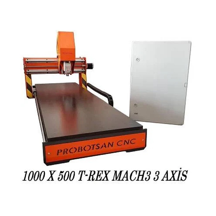
Building a mini CNC router machine requires a careful selection of components to ensure precision, reliability, and performance. Here’s a detailed breakdown of the essential parts:
1. Mechanical Structure (Frame and Motion System)
- Chassis/Frame: The foundation of your CNC. Aluminum extrusions (e.g., 2020, 2040, 4040 profiles) are popular for their balance of strength, lightweight, and ease of assembly. Steel or thick MDF can also be used for specific applications. The frame’s rigidity is paramount to minimize vibrations and ensure machining accuracy.
- Linear Guide Rails: Provide smooth and precise linear motion for the axes (X, Y, Z). Options include polished steel rods with linear bearings (LM8UU, SC8UU), V-slot wheels on aluminum extrusions, or more robust linear guide rails (e.g., HGR series) for higher loads and precision.
- Lead Screws or Ball Screws: Convert rotational motion from the motors into linear motion. Lead screws (e.g., T8 trapezoidal lead screws) are cost-effective and suitable for hobby or light-duty applications. Ball screws offer significantly higher precision, reduced backlash, and greater efficiency, making them ideal for industrial-grade mini CNCs.
- Couplings: Connect the motor shafts to the lead/ball screws. Flexible couplings compensate for minor misalignments, while rigid couplings are used when perfect alignment is achievable and high torque transmission is required.
- Bearings: Support the lead/ball screws and other rotating parts, reducing friction and ensuring smooth operation.
2. Electronic System (Control and Power)
- Stepper Motors: The workhorses for axis movement. NEMA 17 (for lighter loads) or NEMA 23 (for heavier loads and higher torque) are common choices. Ensure the motor’s torque rating matches the expected load and acceleration requirements.
- Stepper Drivers: Control the current to the stepper motors, translating micro-controller signals into motor movements. Popular drivers include A4988, DRV8825 (for smaller motors), and TB6600, DM542 (for NEMA 23 and larger motors). Microstepping capabilities of drivers are important for smoother motion and higher resolution.
- CNC Control Board: The brain of the system. Arduino Uno with a CNC Shield (running GRBL firmware) is a popular and affordable option for DIY mini CNCs. More advanced controllers like the Smoothieboard or dedicated industrial CNC controllers offer greater features and processing power.
- Power Supply Unit (PSU): Provides stable DC power to the motors, drivers, and control board. The voltage (e.g., 12V, 24V) and current capacity must be sufficient for all connected components, especially considering the peak current draw of the motors.
- Spindle Motor: The cutting tool’s power source. For light materials like wood or plastic, a DC brushed motor (e.g., 300W, 500W) is often used. For harder materials or higher precision, a brushless DC (BLDC) motor or an AC spindle motor with a VFD (Variable Frequency Drive) is preferred, offering higher RPM, better torque, and longer lifespan.
- Spindle Driver/Controller: If using a BLDC or AC spindle, a dedicated driver or VFD is needed to control its speed and power.
- Limit Switches (End Stops): Essential safety features that define the physical limits of each axis, preventing the machine from crashing.
- Emergency Stop (E-stop) Button: A critical safety component that immediately cuts power to all motors and the spindle in case of an emergency.
- Wiring and Cable Management: Proper wiring is crucial for signal integrity and safety. Use shielded cables for motor connections to reduce electrical noise. Cable chains can help organize and protect wires.
3. Software Infrastructure (Design and Control)
- CAD (Computer-Aided Design) Software: Used to create 2D drawings or 3D models of the parts you want to machine. Examples include Fusion 360, SolidWorks, AutoCAD, FreeCAD, and SketchUp.
- CAM (Computer-Aided Manufacturing) Software: Converts your CAD model into toolpaths and generates the G-code that the CNC machine understands. Popular CAM software includes Estlcam, Fusion 360 CAM, VCarve Pro, Aspire, and MeshCAM. This software allows you to define cutting parameters like tool diameter, cutting depth, feed rate, and spindle speed.
- G-code Sender Software: Communicates with the CNC control board, sending the G-code line by line to execute the machining process. Examples include Universal Gcode Sender (UGS), GRBL Panel, Candle, and bCNC.
- Firmware: Software loaded onto the CNC control board (e.g., GRBL for Arduino-based systems) that interprets the G-code and controls the motors.
Assembly Process and Critical Considerations
The assembly of a mini CNC machine requires meticulous attention to detail to ensure optimal performance and safety. Here’s a step-by-step guide with critical considerations:
1. Frame Assembly
- Foundation First: Begin by assembling the main frame. Ensure all connections are square and rigid. Use corner brackets and appropriate fasteners to create a stable base. Any wobbles or misalignments here will propagate throughout the machine, affecting precision.
- Leveling: Once assembled, ensure the frame is perfectly level. Use a spirit level on all axes.
2. Linear Motion System Installation
- Rail Alignment: Install the linear guide rails or rods. Precision is key here. Misaligned rails will cause binding, increased friction, and reduced accuracy. Use shims if necessary to achieve perfect parallelism.
- Lead/Ball Screw Mounting: Mount the lead or ball screws, ensuring they are perfectly parallel to their respective linear guides. Secure the end supports firmly.
- Nut Block Attachment: Attach the lead screw nut blocks (or ball nut housings) to the moving gantry or spindle carriage. Ensure smooth, free movement along the entire travel range without any binding.
3. Motor and Coupling Installation
- Motor Mounting: Mount the stepper motors securely to their respective axes. Ensure they are aligned with the lead/ball screws to prevent unnecessary stress on the couplings.
- Coupling Connection: Connect the motor shafts to the lead/ball screws using appropriate couplings. Hand-turn the screws to check for smooth rotation and ensure there’s no excessive play or binding.
4. Spindle Mounting
- Secure Attachment: Mount the spindle motor securely to the Z-axis carriage. Ensure it is perpendicular to the work surface. The spindle mount should be robust enough to handle cutting forces without flexing.
- Tool Clearance: Verify that the spindle has adequate vertical travel (Z-axis) for your intended cutting depths and tool lengths.
5. Electronics Wiring
- Control Board Installation: Mount the CNC control board in a protected enclosure to shield it from dust and debris.
- Motor Wiring: Connect the stepper motors to their respective drivers, paying close attention to the wiring diagrams (phase A, B, etc.). Incorrect wiring can damage motors or drivers.
- Power Supply Connection: Connect the power supply to the control board and stepper drivers. Double-check polarity.
- Spindle Wiring: Wire the spindle motor and its driver/VFD according to the manufacturer’s instructions.
- Limit Switches and E-stop: Connect limit switches and the E-stop button to the control board. Test their functionality before running any programs.
- Cable Management: Route all cables neatly and secure them with cable ties or cable chains. This prevents tangles, reduces wear, and minimizes electrical interference.
6. Software Setup and Calibration
- Firmware Upload: Upload the GRBL firmware (or other chosen firmware) to your control board (e.g., Arduino).
- Software Installation: Install your chosen G-code sender software on your computer.
- Axis Testing: Test each axis individually using the G-code sender. Verify that movements are in the correct direction (X+, X-, Y+, Y-, Z+, Z-). If not, adjust motor wiring or firmware settings.
- Calibration: Calibrate the steps per millimeter for each axis. This involves moving an axis a known distance (e.g., 100mm) and measuring the actual travel. Adjust the steps/mm parameter in the firmware until the actual travel matches the commanded travel.
- Limit Switch Testing: Verify that all limit switches trigger correctly and halt axis movement.
- Spindle Test: Test the spindle’s on/off and speed control functionality.
Safety Protocols and Maintenance
Operating any CNC machine, even a mini one, requires strict adherence to safety protocols and regular maintenance to ensure longevity and prevent accidents.
Safety Protocols:
- Eye Protection: Always wear safety glasses or a face shield to protect against flying debris.
- Hearing Protection: Depending on the material and cutting tool, CNC operations can be noisy. Use earplugs or earmuffs.
- Dust and Fume Extraction: Machining generates dust (wood, plastic) or fumes (some plastics, metals). Use a dust collection system or work in a well-ventilated area. For certain materials, a fume extractor is essential.
- Emergency Stop Accessibility: Ensure the E-stop button is always easily accessible and functional. Test it regularly.
- Clear Work Area: Keep the work area clean and free of clutter. Loose clothing, long hair, and jewelry can get caught in moving parts.
- Tool Handling: Always handle cutting tools with care. They are sharp and can cause injury.
- Machine Guarding: If possible, enclose the working area with clear guards to contain chips and prevent accidental contact with moving parts.
- Power Disconnection: Always disconnect power to the machine before performing any maintenance, tool changes, or adjustments.
- Never Leave Unattended: Do not leave the machine running unattended, especially during initial runs or when working with new materials/toolpaths.
Maintenance:
- Lubrication: Regularly lubricate lead screws, ball screws, and linear guide rails according to manufacturer recommendations. This reduces friction, wear, and extends component life.
- Cleaning: Keep the machine clean. Remove chips, dust, and debris from the work area, rails, and screws after each use. Accumulated debris can cause binding and wear.
- Fastener Check: Periodically check all fasteners (bolts, screws, nuts) for tightness. Vibrations can cause them to loosen over time, affecting rigidity and accuracy.
- Belt Tension (if applicable): If your machine uses timing belts, check their tension regularly. Loose belts can lead to backlash and inaccurate movements.
- Tool Inspection: Inspect cutting tools before each use for sharpness and damage. Dull or damaged tools can lead to poor cut quality, increased tool wear, and excessive load on the spindle motor.
- Spindle Maintenance: Check the spindle motor for unusual noises or vibrations. Ensure proper cooling.
- Electrical Connections: Periodically inspect all electrical connections for signs of wear, corrosion, or looseness.
- Software Updates: Keep your firmware and G-code sender software updated to benefit from bug fixes and new features.
Conclusion: The Power of Compact Precision
The construction of a mini CNC machine represents a significant step towards democratizing precision manufacturing and rapid prototyping. As this guide has demonstrated, understanding the interplay between mechanical, electronic, and software components is crucial for successful implementation. From selecting the right frame materials to meticulously wiring stepper motors and calibrating axis movements, each step contributes to the overall accuracy and reliability of the system. Mini CNCs empower engineers, designers, and small businesses to iterate quickly, test concepts efficiently, and produce customized parts with a level of detail previously reserved for larger, more expensive industrial machines. Their versatility makes them invaluable assets in R&D labs, educational institutions, and specialized production environments where space and budget are considerations. By adhering to the technical specifications outlined and prioritizing safety protocols, users can unlock the full potential of these compact powerhouses, driving innovation and efficiency in their respective fields. The ability to bring complex digital designs to life with such accessible technology underscores the transformative impact of mini CNCs on modern manufacturing. For those looking to integrate advanced CNC capabilities into their operations, Mermak CNC offers a range of industrial-grade components and complete solutions. We invite you to explore our offerings and request a quote on WhatsApp to discuss how our expertise can support your next project.
FAQ
What is a mini CNC machine and what are its primary uses?
A mini CNC machine is a compact, computer-controlled device used for precision machining of materials like wood, plastic, and soft metals. It operates by interpreting G-code commands to move a cutting tool along multiple axes (X, Y, Z) to create intricate shapes and designs. They are ideal for prototyping, small-batch production, education, and hobbyist projects.
What are the essential components required to build a mini CNC machine?
The core components include a rigid mechanical frame (often aluminum extrusions), linear motion systems (guide rails, lead/ball screws), stepper motors with drivers, a CNC control board (e.g., Arduino with GRBL firmware), a power supply, and a spindle motor. Software for CAD, CAM, and G-code sending is also essential.
How does a mini CNC machine work, from design to execution?
The operating principle involves CAD software for design, CAM software to generate G-code (tool paths), and a G-code sender to transmit these commands to the CNC control board. The control board then interprets the G-code and sends signals to the stepper motor drivers, which in turn move the motors and the cutting tool along the specified axes to machine the material.
What factors influence the precision and accuracy of a mini CNC machine?
Key factors include the rigidity of the frame, the precision of linear motion components (ball screws offer higher precision than lead screws), the step angle of the stepper motors, and the microstepping settings of the drivers. Proper calibration of steps per millimeter is also crucial for achieving high accuracy.
What safety precautions should be taken when operating a mini CNC machine?
Safety is paramount. Always wear eye and hearing protection. Ensure the emergency stop button is easily accessible and functional. Use dust extraction or work in a well-ventilated area. Keep the work area clear of clutter and disconnect power before any maintenance or adjustments. Never leave the machine running unattended.


