No products in the cart.
Assembling a CNC Frame with Sigma Profiles: Rigidity Tips for Industrial Buyers
Contents
Sigma Profile CNC Frame Assembly and Rigidity Tips: A Field Guide and Technical Article
Introduction and Technical Analysis
In the industrial automation sector, particularly in CNC machine manufacturing and integration, the frame structure critically impacts the machine’s overall performance, precision, and lifespan. As an alternative to traditional welded steel constructions, sigma profile (aluminum extrusion profile) systems have gained widespread use due to their modular design, lightweight nature, aesthetic appearance, and ease of processing. However, it is essential for a CNC frame built with these profiles to possess adequate rigidity and vibration damping characteristics, especially in applications requiring high-speed and precise machining. This technical article and field guide aim to provide industrial automation professionals with a comprehensive roadmap by detailing the engineering principles, design approaches, critical considerations, and methods for increasing rigidity during the sigma profile CNC frame assembly process. We will examine the topic across a broad spectrum, from material science to fastener selection, assembly techniques to vibration analysis, blending practical field experience with technical knowledge.
Operating Principles and Technical Data
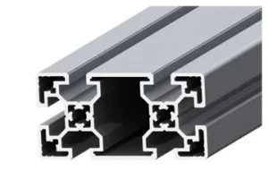
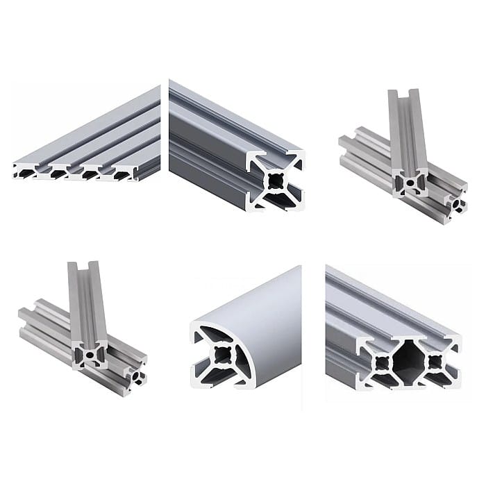
Sigma profiles are structural elements typically produced from 6000 series aluminum alloys (e.g., 6063-T5 or 6061-T6) via extrusion, featuring standardized T-slot channels. These channels allow for easy mounting of other profiles, panels, sensors, or actuators using special fasteners and T-nuts. The use of these profiles in CNC frame design offers advantages such as rapid prototyping, easy modification, and disassemblability, while also introducing fundamental engineering parameters like rigidity, which directly affect the machine’s performance under dynamic loads. The precision and repeatability of a CNC machine are closely related to how resistant its frame is to bending, torsional, and vibrational deformations. A frame with insufficient rigidity can flex under cutting forces, acceleration/deceleration effects, and motor vibrations, leading to machining errors, poor surface quality, and reduced tool life.
Key engineering factors influencing frame rigidity include:
- Material Properties: Aluminum’s modulus of elasticity (approximately 70 GPa) is lower than that of steel (approximately 200 GPa). This means aluminum will be less rigid than steel for the same cross-sectional area. However, aluminum’s low density allows for achieving sufficient rigidity without a significant increase in weight by using profiles with larger cross-sectional areas.
- Profile Geometry and Moment of Inertia: The bending rigidity of a profile is directly proportional to its cross-sectional moment of inertia (I). Larger profiles (e.g., 80x160mm instead of 40x80mm) or those with more complex cross-sections offer a higher moment of inertia, increasing bending resistance. Closed or box-section profiles are particularly effective for torsional rigidity.
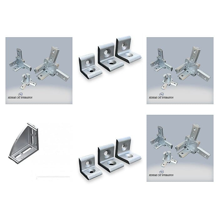
- Fasteners and Connection Methods: How profiles are joined is one of the most critical factors determining the overall rigidity of the frame. Bolted connections are generally considered less rigid than welded connections. However, the rigidity of bolted systems can be significantly enhanced with specially designed high-strength corner brackets, internal connectors, and connection plates. The number and quality of connection points directly impact the efficiency of load transfer.
- Structural Design and Support: The geometric arrangement of the frame, the length of beam spans, the use of cross-bracing, and load distribution play a significant role in rigidity. Unsupported long beams are more prone to bending deformations. Triangular supports and closed-loop structures are effective in increasing torsional rigidity.
In CNC frame design, it is essential for the frame to maintain stability not only under static loads but also under dynamic loads (acceleration/deceleration, cutting forces, vibrations). Therefore, tools like finite element analysis (FEA) can be used during the design process to identify potential weak points and resonance frequencies in advance. Keeping the frame’s natural frequencies away from the machine’s operating frequencies is vital to reduce the risk of resonance and prevent vibration-induced errors. Furthermore, the rigidity and precision of the interface between linear motion systems (linear guide rails, ball screws) and the frame directly affect overall machine performance. Rails must be mounted precisely and evenly to the frame, all contact surfaces must be properly machined, and adequate tightening torques must be applied.
| Parameter | Value/Description |
|---|---|
| Profile Type (General) | Industrial Aluminum Extrusion Profiles (Sigma Profile) |
| Material | Aluminum Alloy (Typically EN AW-6063 T5 or EN AW-6061 T6) |
| Surface Treatment | Anodized Coating (Typically 10-20 microns) |
| Modulus of Elasticity (E) | ~70 GPa (70 x 10^9 N/m²) |
| Density | ~2.7 g/cm³ |
| Moment of Inertia (Ix, Iy) | Varies by profile size and cross-sectional geometry (Must be checked against manufacturer datasheet values.) |
| Torsional Rigidity (J) | Depends on the profile’s closed cross-sectional area and wall thickness (Must be checked against manufacturer datasheet values.) |
| Fastener Type | T-nut, Bolt, Corner Bracket, Internal Connector, Connection Plate |
| Application Area | CNC Frames, Automation Machines, Test Benches, Protective Enclosures, Conveyor Systems |
Field Considerations
- Correct Profile Selection and Sizing: The appropriate profile series (e.g., 40×40, 45×90, 80×80) and wall thickness must be selected based on the application’s load, speed, acceleration, and precision requirements. Especially in bridge-type or gantry-type CNC machines, the bending and torsional rigidity of the main beams (X-axis) are critically important. Long spans should be avoided; if necessary, larger cross-section or reinforced profiles should be preferred. For the primary load-bearing elements of the frame, always consider the largest available profiles.
- Optimal Connection Methods: The modularity of sigma profiles offers various fasteners. However, not all connection methods are equal in terms of rigidity. The most rigid connections are typically achieved using “internal connectors” or “heavy-duty corner brackets.” Standard corner brackets may loosen over time or fail to provide sufficient rigidity, especially under high dynamic loads. Ensure connection surfaces are clean and flat, all bolts are tightened to the manufacturer’s specified torque values, and checked periodically. Using multiple connection points distributes the load, increasing rigidity.
- Structural Reinforcement and Cross-Bracing: In critical areas of the frame, especially where dynamic loads are concentrated, additional cross-bracing or triangular support structures should be used. Such reinforcements significantly increase the frame’s torsional resistance and minimize bending deformations. Creating closed-loop structures provides much higher rigidity compared to open-frame designs. Additionally, ensure the frame is mounted to the floor or main support platform with sturdy, vibration-damping feet.
- Integration of Linear Motion Systems: Mounting precise motion components like linear guide rails and ball screws to the frame is an engineering discipline in itself, independent of the frame’s overall rigidity. The profile surfaces where the rails will be mounted must be machined with high precision (milling, grinding) and offer excellent flatness and parallelism. The mounting bolts for the rails must be tightened to equal torque according to manufacturer specifications, ensuring no gaps or stresses are created. If necessary, micro-gaps can be filled using epoxy or special shims under the rails to provide a wider contact area.
- Vibration Damping and Resonance Management: Vibrations in CNC machines are one of the most significant factors reducing machining quality and shortening machine life. Natural frequency analysis should be performed during frame design to avoid operating frequencies close to the machine’s natural frequencies. Additionally, vibration-damping pads or isolators should be added to the frame feet, and viscoelastic damping materials (e.g., polymer-based damping plates) can be integrated at critical points. A heavy and rigid frame generally has better vibration damping properties, but sometimes using damping materials can be more efficient than adding mass.
- Assembly Precision and Control: Cutting and drilling tolerances for all profiles and fasteners must be carefully checked. During frame assembly, laser alignment devices, spirit levels, and precision angle gauges should be used to ensure each element is in the correct position and angle. After assembly, the overall flatness, parallelism, and perpendicularity of the frame must be checked, and adjustments made if necessary. A loose or incorrectly mounted connection compromises the rigidity of the entire frame.
Common Problems and Solutions
Problem 1: Insufficient Frame Rigidity and Vibrations During Machining
Scenario: The CNC machine exhibits noticeable vibrations, especially when operating at high speeds or during deep cuts, leading to chatter marks on the workpiece surface or deviations in dimensional accuracy.
Analysis: This situation typically arises from insufficient profile cross-sectional area, weak fasteners, or structural weaknesses in the frame design. The frame’s natural frequency might be close to the machine’s operating frequencies.
Solution:
- Profile Reinforcement: Replace load-bearing beams with larger cross-section profiles or fill existing profiles with steel or aluminum filler materials (epoxy granite, sand, etc.) to increase mass and damping properties.
- Connection Optimization: Use internal connectors or high-strength plate connections instead of standard corner brackets. Ensure all connection bolts are correctly tightened with a torque wrench and checked periodically.
- Structural Reinforcement: Add cross-bracing or triangular supports at critical points of the frame (especially where X and Y axis carriers meet). Create closed-loop structures to increase torsional rigidity.
- Vibration Damping: Install industrial-grade vibration-damping pads on the frame feet. Integrate damping mats or viscoelastic materials into the machine base or inside the frame.
Problem 2: Parallelism and Flatness Errors in Linear Guide Rails
Scenario: Sticking, friction noises, or excessive motor strain during axis movements. Conicity or angular errors appearing on the workpiece.
Analysis: This is caused by insufficiently flat profile surfaces where the rails are mounted, misalignment during assembly, or stresses resulting from uneven tightening of bolts.
Solution:
- Surface Machining: Precisely mill or grind the profile surfaces where the rails will be mounted. Aim for a tolerance of <0.02mm/meter for surface flatness and parallelism.
- Alignment Procedure: Use laser alignment devices or precision dial indicators to ensure perfect parallelism and flatness of the rails relative to each other and the frame.
- Bolt Tightening Sequence: Tighten rail mounting bolts gradually and evenly, from the inside out or from the center to the edges, according to the manufacturer’s recommended torque values. Avoid overtightening bolts to prevent stress in the rails.
- Gap Filling: Using precision epoxy or special shims to fill micro-gaps under the rails can improve rigidity and load distribution by increasing the contact surface.
Problem 3: Loosening or Deformation at Connection Points
Scenario: The machine loses precision over time, gaps appear between frame elements, or mounting bolts loosen.
Analysis: This is due to repetitive dynamic loads, insufficient tightening torque, inappropriate fasteners, or material fatigue.
Solution:
- Correct Fastener Selection: Use high-strength steel T-nuts and bolts. For critical connections, prefer self-locking nuts or spring washers.
- Torque Control: Tighten all connection bolts with a torque wrench according to manufacturer specifications. Perform torque checks after assembly and during periodic maintenance.
- Additional Connection Points: Use more fasteners in areas where loads are concentrated to distribute the load over a wider area.
- Structural Reinforcement Plates: Add extra aluminum or steel connection plates at critical connection points to increase surface contact area and rigidity.
Expert Advice
Assembling a CNC frame with sigma profiles offers significant advantages in terms of efficiency, flexibility, and cost-effectiveness within the industrial automation sector. However, to fully leverage these benefits, great attention must be paid to fundamental engineering principles such as rigidity, precision, and vibration management. From an expert perspective, a successful sigma profile CNC frame project not only involves selecting the right profiles and fasteners but also requires comprehensive engineering analysis (like FEA) during the design phase, precise manufacturing, and a meticulous assembly process. The primary purpose of the frame is to support motion systems and machining forces with minimal deformation, ensuring the machine’s nominal precision and repeatability. Therefore, every detail, such as the profile’s cross-sectional area and moment of inertia, the quality and number of connection points, the correct placement of structural reinforcements, and vibration damping strategies, is vital for the project’s success. Field experience shows that a small design or assembly error made at the outset can lead to high maintenance costs, poor machining quality, and production losses throughout the machine’s lifespan. For this reason, material selection of the highest quality standards, detailed engineering calculations, and assembly processes carried out by experienced personnel should always be preferred. In the future, the performance of sigma profile frames can be further optimized with smart sensors and AI-powered vibration monitoring systems, leading to the widespread adoption of adaptive and self-optimizing CNC machines in line with Industry 4.0 principles. It is critically important for professionals in this field to closely follow developments in material science, mechanical design, and automation technologies to remain competitive and offer innovative solutions.
FAQ
What are sigma profiles and why are they used in CNC frames?
Sigma profiles are industrial aluminum extrusion profiles with T-slots, typically made from 6000 series aluminum alloys. They are used to construct modular frames for CNC machines, automation equipment, and other industrial structures due to their lightweight, ease of assembly, and flexibility.
Why is frame rigidity so important for a CNC machine?
Rigidity is crucial for CNC frames because it directly impacts machining precision, surface quality, and tool life. A rigid frame resists bending, torsion, and vibration, ensuring stable operation under dynamic loads and preventing errors like chatter marks or dimensional inaccuracies.
What are the best ways to increase the rigidity of a sigma profile CNC frame?
To enhance rigidity, select larger cross-section profiles, use high-strength internal connectors or heavy-duty corner brackets, incorporate cross-bracing and closed-loop structures, and ensure precise assembly with correct bolt torques. Filling profiles with damping materials can also increase mass and vibration absorption.
What are common problems encountered when assembling CNC frames with sigma profiles, and how can they be solved?
Common issues include insufficient rigidity leading to vibrations, parallelism/flatness errors in linear guide rails, and loosening connections. Solutions involve profile reinforcement, optimizing connection methods, structural bracing, precise surface machining for rails, and using appropriate fasteners with controlled torque.
How should linear guide rails be integrated into a sigma profile frame for optimal performance?
Proper integration of linear guide rails involves precisely machined profile surfaces for mounting, ensuring perfect parallelism and flatness using alignment tools, and tightening mounting bolts evenly to manufacturer specifications to avoid stress. Using shims or epoxy can fill micro-gaps for better contact.