
No products in the cart.
%60 Discount


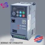
1.5 kW 220V Motor Drive Inverter
Original price was: 257.33$.102.94$Current price is: 102.94$.
High-performance series inverter for industrial automation. Control speed, torque, and direction of 3-phase asynchronous motors from a single-phase 220V AC supply.
In stock
🔥 Special for Today Only %60 Discount Opportunity!📦 Category: 220V Speed Control Devices🏷️ Power: 1.5 kW🏷️ Supply Voltage: 220V
Mermak assuranceFrom factory to end user · importer / main dealer · strong stock
ImporterMain dealer / distributorStrong stockGood priceCorporate invoice
In stock / available to order · 14-day return for standard unused products; conditions may vary for custom size/cut products.
1.5 kW 220V Motor Drive Inverter
INDUSTRIAL AUTOMATION PARTS | SUPERIOR PERFORMANCE SERIES
Detailed Product Review
The K10-2S01R5G model 1.5 kW Motor Drive Inverter (VFD) is a power electronics device designed to control the speed, torque, and direction of industrial 3-phase asynchronous motors. Its fundamental operating principle involves converting the alternating current (AC) from the mains supply into direct current (DC) using a rectifier, storing this DC voltage on a DC bus, and finally converting it back into AC with the desired frequency and amplitude using an inverter (IGBT-based switching circuit) via Pulse Width Modulation (PWM) technique. This conversion process allows for precise adjustment of the motor’s synchronous speed and consequently its rotor speed by simultaneously changing the frequency and amplitude of the voltage applied to the motor’s stator windings. Its single-phase 220V AC input capability is particularly significant, enabling the full potential of 3-phase motors to be utilized in workshops, homes, or small-scale industrial environments where a 3-phase infrastructure may not be available. The device employs an advanced scalar V/F (Voltage/Frequency) control algorithm, enabling it to dynamically adapt to motor shaft load variations and maintain stable operation while ensuring the motor’s magnetic flux remains constant for efficient performance.
The material construction of this motor drive is engineered with high power density and thermal management principles in mind. The power stage utilizes IGBT (Insulated Gate Bipolar Transistor) modules, fast-switching diodes, and high-capacity electrolytic capacitors, all selected for their high switching speeds and current-carrying capabilities. The control board features a microcontroller unit that processes motor parameters, generates PWM signals, and executes protection algorithms. Thermal management is achieved through integrated aluminum heat sinks and an intelligent temperature-sensitive fan control system that adjusts fan speed based on the drive’s internal temperature, ensuring optimal cooling performance and energy efficiency. For system integration, the drive provides U, V, W terminals for motor connection, R, S/L, N terminals for mains connection, and digital inputs/outputs, analog inputs (for potentiometer or 0-10V/4-20mA signals for speed reference), and relay outputs for control signals. This configuration facilitates easy integration with external control panels, PLCs, or HMIs. Its applications span a wide range, from precise speed control of CNC spindle motors and speed adjustment in woodworking machinery (lathes, mills, band saws) to synchronization of conveyor belts and mixers in the food and packaging industries, energy-efficient operation of fans and pumps in HVAC systems, and soft-start/stop applications in textile machinery. Notably, for high-speed spindle motors reaching up to 24,000 RPM, the ability to adjust the frequency up to 400 Hz is a critical feature directly impacting cutting precision and surface quality.
Advantages of the 1.5 kW 220V Motor Drive Inverter
Optimized Torque Performance: This drive ensures the motor delivers performance close to its nominal torque capacity even at low speeds, thanks to advanced torque compensation algorithms. It dynamically adjusts the V/F curve, especially during motor startup or sudden load changes, to minimize torque drops and optimize the current flowing through the motor windings. This technique maintains a stable operating state by preventing speed reduction even when the load on the motor shaft increases. For instance, in a CNC spindle motor, maintaining constant RPM despite increased cutting load is crucial for preserving machining quality and precision. This allows for maximum efficiency from the 1.5 kW motor power and prevents undesirable conditions like motor stalling.
Energy Efficiency: The motor drive inverter significantly reduces unnecessary energy consumption by adjusting the motor speed according to the instantaneous requirements of the application. In variable torque applications like fans, pumps, and compressors, reducing motor speed leads to a cubic decrease in power consumption (P ∝ N^3). For example, a 20% reduction in fan speed can result in approximately a 50% decrease in power consumption. This drive ensures the motor draws only the necessary amount of energy, thereby increasing the overall energy efficiency of the system. Furthermore, its soft-start and soft-stop features eliminate the high inrush currents during motor startup, reducing stress on the mains supply and extending the motor’s lifespan.
Comprehensive Motor and Drive Protection: The K10-2S01R5G model drive is equipped with an integrated suite of protection functions that safeguard both the drive and the connected motor against electrical and mechanical stresses. These functions include overcurrent protection (against high currents from motor winding short circuits or overloads), overvoltage and undervoltage protection (against mains voltage fluctuations), phase loss protection (to prevent single-phase operation of the motor if an input or output phase is lost), over-temperature protection (to stop the system and prevent damage if the drive’s IGBT modules or motor exceed thermal limits), and short-circuit protection. These protection mechanisms safely shut down the system during fault conditions, preventing equipment damage, reducing maintenance costs, and enhancing overall system reliability.
Technical Specifications and Capacity
Specification | Value/Description
Model Code | K10-2S01R5G
Power Capacity | 1.5 kW / 2 HP
Input Voltage | 1 Phase 220V AC ±15%
Output Voltage | 3 Phase 0-220V AC
Nominal Output Current | 7.5 A
Output Frequency Range | 0.1 ~ 400 Hz
Overload Capacity | 150% (60 seconds)
Technical Frequently Asked Questions (FAQ)
What is V/F control mode and how is it implemented in this drive?
V/F (Voltage/Frequency) control mode is one of the most basic and common methods used for speed control of asynchronous motors. In this mode, the ratio between the voltage (V) applied to the motor’s stator windings and the frequency (F) is kept constant (V/F = Constant). The primary goal of this principle is to maintain the motor’s magnetic flux (Φ) at its nominal value. Since the inductive reactance of the motor changes proportionally with frequency (XL = 2πfL), the voltage must be reduced proportionally as the frequency decreases to prevent motor saturation or magnetic flux weakening. The K10-2S01R5G drive manages this V/F ratio through internal algorithms. Especially at low frequencies, where the motor’s stator resistance becomes more significant, the drive typically applies an IR drop compensation, slightly increasing the voltage to maintain the motor’s nominal torque. This prevents the motor from stalling in applications requiring high torque at low speeds, ensuring stable operation. Users can optimize application-specific torque requirements by selecting linear, quadratic, or multi-point V/F curves via the drive’s parameters.
What is the principle behind a single-phase input drive powering a three-phase motor?
The principle of a single-phase input motor drive powering a three-phase motor relies on power electronics and consists of three main stages. In the first stage, the single-phase 220V AC voltage from the mains is converted into direct current (DC) using a diode bridge or a similar rectifier circuit. This DC voltage is then stored on a DC bus in the second stage, typically using large-capacity electrolytic capacitors to filter voltage fluctuations and achieve a stable DC voltage level. In the third and final stage, this stable DC voltage is converted back into alternating current by an inverter bridge composed of high-speed switching elements like IGBTs (Insulated Gate Bipolar Transistors). The inverter simulates three-phase sinusoidal voltage waveforms at the desired frequency and amplitude at the output by switching these elements on and off in a specific sequence and frequency using Pulse Width Modulation (PWM) technique. This process effectively converts the energy from the single-phase mains supply into the three-phase, variable-frequency, variable-voltage energy required to operate a three-phase asynchronous motor. This conversion makes it possible to use three-phase motors in locations lacking a three-phase grid infrastructure.
What does the drive’s overload capacity (150%, 60 seconds) mean, and how does it play a role in motor selection?
The drive’s overload capacity of 150% (60 seconds) means that the device can safely supply up to 150% of its nominal output current for a maximum duration of 60 seconds. For example, with this 1.5 kW drive’s nominal output current of 7.5 A, it can tolerate currents up to 11.25 A for one minute during startup or sudden load increases. This feature is critical for applications where motors draw up to 5-7 times their nominal current during startup or require short bursts of high torque during operation. The overload capacity allows the drive to meet these temporary high current demands, ensuring smooth motor acceleration or adaptation to load changes. In motor selection, this parameter determines whether the drive can meet the motor’s dynamic requirements. If the application requires continuous operation above nominal current, or if startup currents exceed the drive’s overload capacity and duration, a higher capacity drive may need to be selected, or the motor’s nominal power might need to be derated relative to the drive. This reduces thermal stress on the drive and extends its lifespan.
What installation recommendations should be considered for the drive’s EMC (Electromagnetic Compatibility) performance?
Due to the high-frequency switching nature of motor drives, they have the potential to emit electromagnetic interference (EMI). To optimize EMC performance and minimize interaction with other electronic devices in the vicinity, several installation recommendations should be considered. Firstly, the grounding connections for the drive and the motor must be robust and low-impedance, in accordance with local electrical standards; preferably, a single-point grounding principle should be applied. Secondly, the power cables between the drive and the motor should be shielded (screened), with the shield grounded 360 degrees at the drive end. This shielding prevents the propagation of high-frequency noise. Thirdly, power cables (input AC, output motor) should be physically separated from control and signal cables (analog inputs, digital inputs) and should not be run in parallel for long distances; this prevents noise transfer via inductive coupling. Fourthly, adding an EMC filter (RFI filter) at the mains input reduces the high-frequency noise radiated by the drive back into the mains. Finally, the enclosure or panel where the drive is mounted should be metal and well-grounded, acting as a Faraday cage to prevent electromagnetic fields from escaping. These measures enhance the overall electromagnetic compatibility of the system, ensuring a reliable and stable operating environment. We supply to countries such as the United Kingdom, United States, Canada, Australia, Ireland, New Zealand, and South Africa, as well as similar international markets.
| Power | 1.5 kW |
|---|---|
| Supply Voltage | 220V |
You must be logged in to post a review.
Taksit Tablosu
Related Products
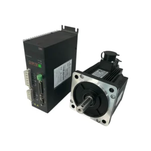 %40 Discount1.5 kW Servo Motor Set 130ST-M06025 T3A-L30F-RABFOriginal price was: 864.26$.520.38$Current price is: 520.38$.View
 %42 Discount1kW Servo Motor Set 80AST-A1C04025 T3D-L20A-RABFOriginal price was: 408.04$.236.23$Current price is: 236.23$.View
 %60 Discount4 kW 380V Motor Drive InverterOriginal price was: 367.56$.147.02$Current price is: 147.02$.View
Reviews
There are no reviews yet.