
No products in the cart.
%60 Discount


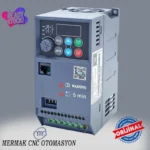
1.5 kW 380V Motor Drive Inverter
Original price was: 264.67$.105.86$Current price is: 105.86$.
High-performance Variable Frequency Drive (VFD) for industrial three-phase asynchronous motors. Features Sensorless Vector Control (SVC) and V/F control for precise speed, torque, and direction management.
Only 0 left in stock
🔥 Special for Today Only %60 Discount Opportunity!📦 Category: 380V Speed Control Devices🏷️ Power: 1.5 kW🏷️ Supply Voltage: 380V
Mermak assuranceFrom factory to end user · importer / main dealer · strong stock
ImporterMain dealer / distributorStrong stockGood priceCorporate invoice
In stock / available to order · 14-day return for standard unused products; conditions may vary for custom size/cut products.
1.5 Kw 380v Motor Drive Inverter
INDUSTRIAL AUTOMATION PARTS | SUPERIOR PERFORMANCE SERIES
Detailed Product Review
This 1.5 kW (2 HP) 380V Motor Drive Inverter is a Variable Frequency Drive (VFD) designed to control the speed, torque, and direction of industrial three-phase asynchronous motors. Its fundamental operating principle involves converting the fixed voltage and frequency AC power from the grid into DC power via a rectifier, and then transforming this DC voltage into variable amplitude and variable frequency AC voltage using Pulse Width Modulation (PWM) technique through an inverter stage. This process allows for precise adjustment of the voltage and frequency applied to the motor’s stator windings, enabling control over the motor’s synchronous speed and consequently its rotor speed. Featuring both Sensorless Vector Control (SVC) and V/F (Voltage/Frequency) control algorithms, this model estimates the motor’s magnetic flux and rotor position, delivering high starting torque and dynamic response even at low speeds. This optimizes the motor’s adaptation to sudden load changes and enhances energy efficiency, while the soft start and stop ramps minimize wear and tear on mechanical systems.
The K10-4T01R5G model drive boasts a robust construction designed to withstand the demanding conditions of industrial environments. Internally, it incorporates IGBT (Insulated Gate Bipolar Transistor) modules for high switching speeds and reduced power loss, high-capacity DC bus capacitors, and an advanced microprocessor-based control board. These components are integrated on a PCB designed in compliance with Electromagnetic Compatibility (EMC) standards. The device’s external casing is made from dust and moisture-resistant materials conforming to IP protection ratings, and an optimized cooling system (with intelligent fan control) ensures long-term, reliable operation. For system integration, it can easily communicate with PLC (Programmable Logic Controller) or HMI (Human Machine Interface) systems via standard serial communication protocols like Modbus RTU. This integration capability allows for remote management of functions such as parameter setting, status monitoring, and fault diagnosis within a centralized automation system. Its application areas span a wide range, from CNC machines requiring precise speed and torque control to conveyor systems, fan and pump applications, and textile machinery. It is positioned as a solution for industrial facilities requiring a 380V AC mains supply, extending motor life and reducing operational costs.
1.5 Kw 380v Motor Drive Inverter Advantages
High Dynamic Performance and Torque Control: The K10-4T01R5G model, through its advanced Sensorless Vector Control (SVC) algorithm, directly controls the motor’s stator current vector to achieve precise regulation of rotor flux and torque. This technique enables the motor to produce up to 150% of its nominal torque as starting torque even at low speeds, preventing stalls in applications like mixers, extruders, or conveyor belts that start under heavy load. Vector control improves the motor’s dynamic response, making acceleration and deceleration ramps sharper and more controllable, which is critical for process stability and product quality.
Optimized Energy Efficiency and Cost Reduction: The built-in PID (Proportional-Integral-Derivative) control function continuously monitors process variables (pressure, flow, temperature, etc.) and adjusts the motor’s speed in real-time. Particularly in variable torque applications like pumps and fans, the motor operates only at the required power level instead of running at full capacity. This adaptive control strategy can reduce energy consumption by 30% to 50% by eliminating inefficient operating points at partial loads. Reduced energy consumption directly lowers operating costs while also contributing to a smaller carbon footprint. Furthermore, soft start and stop features improve power quality by eliminating sudden current peaks drawn from the grid.
Comprehensive Integrated Motor and System Protection Functions: This drive is equipped with over 10 built-in protection functions designed to safeguard the connected 1.5 kW motor and the overall system against various electrical and mechanical faults. These include overcurrent, overvoltage, undervoltage, phase loss (input and output), overload (I²t protection), overheating (IGBT and drive), short circuit, and ground fault protection. Each protection mechanism automatically deactivates the drive and motor when specified limit values are exceeded, preventing potential damage. For instance, overcurrent protection prevents stator winding burnout during sudden jams or mechanical failures, while overvoltage protection minimizes IGBT damage from grid fluctuations. This integrated protection package significantly enhances the overall reliability and operational lifespan of the system.
Technical Specifications and Capacity
Feature|Value/Description
Model Code|K10-4T01R5G | Mermak CNC K10 Series, 3 Phase 380V Input, 1.5 kW Power Class
Motor Power|1.5 kW (2 Horsepower / HP) | Maximum continuously operable asynchronous motor power.
Input Supply|3 Phase 380V AC (±15%) | Stable operation with industrial grid voltage tolerance.
Output Current (Nominal)|4.0 Amperes | Capacity to provide continuous nominal current for 1.5 kW motors.
Output Frequency Range|0.1 ~ 400 Hz | Precise and stepless control of motor speed over a wide range.
Overload Capacity|150% for 1 minute | Resistance to instantaneous and short-term high torque demands.
Braking Resistor|Internal / External (Optional) | Regenerative energy management for rapid stopping of high inertia loads.
Cooling System|Intelligent Fan Control | Optimizes fan speed based on thermal load, reducing noise and energy consumption.
Technical Frequently Asked Questions (FAQ)
What is the fundamental difference between Sensorless Vector Control (SVC) and V/F control in this drive, and in which applications should SVC be preferred?
V/F (Voltage/Frequency) control is the most basic control method that attempts to keep the motor’s magnetic flux constant by maintaining a fixed ratio (V/Hz) between the motor’s stator voltage and frequency. This method can control motor speed over a wide range but has limited torque control and dynamic response performance, especially at low speeds, because it lacks direct information about the motor’s actual rotor flux and position. Sensorless Vector Control (SVC), on the other hand, estimates the rotor flux and position by measuring the motor’s stator currents and voltages using complex mathematical models (e.g., observers). This allows the torque and flux components of the motor to be controlled independently. SVC offers high starting torque, more precise speed regulation, and faster dynamic response even at low speeds. Therefore, SVC should be preferred in applications requiring high starting torque or precise speed/torque control, such as mixers, conveyors, and cranes. For applications with variable torque and low dynamic requirements, like fans and pumps, V/F control may be sufficient.
What are the cable types and grounding requirements for the input and output of this 1.5 kW drive?
Selecting cables of appropriate cross-section and type for the drive’s input (mains supply) and output (motor connection) is critical. For the input cable, copper conductor cables with PVC or XLPE insulation, preferably shielded, and of suitable cross-section for 3-phase 380V AC mains should be used. For the output cable, it is essential that the cable from the drive to the motor is shielded. Using shielded cable minimizes electromagnetic interference (EMI/RFI) caused by the drive’s high-frequency switching, reducing adverse effects on other electronic devices and preventing the motor cable from acting as an antenna. The cable shield must be properly connected to the grounding point (PE) on the drive and the motor’s frame. Grounding is vital for both electrical safety and EMI performance. The frames of the drive and motor must be connected to a low-impedance grounding system in accordance with local electrical regulations. The cross-section of the grounding cable should not be less than that of the phase cables, and all connections must be tight and reliable.
What is the function of the internal braking unit in this drive, and when is an external braking resistor required?
The internal braking unit consists of a circuit that monitors the drive’s DC bus voltage and a switching element (typically an IGBT). When the motor decelerates or stops an inertial load, it starts operating in generator mode, converting mechanical energy into electrical energy and feeding it back to the drive’s DC bus. This causes the DC bus voltage to rise. The internal braking unit activates when the DC bus voltage exceeds a certain threshold, diverting this excess energy to a braking resistor (internal or external) where it is dissipated as heat. This keeps the DC bus voltage under control and prevents the drive from tripping on an overvoltage fault. An external braking resistor is particularly necessary in applications where high inertia loads need to be stopped quickly or where frequent start-stop cycles occur. The capacity of the internal braking unit is limited to a certain power; if the amount of regenerative energy exceeds the power that the internal unit and resistor can dissipate, connecting an external, higher-power braking resistor becomes mandatory. This ensures the safe and efficient operation of the drive and the system.
How is the Mermak K10-4T01R5G drive integrated with an automation system (PLC/HMI), and which parameters can be controlled remotely?
The Mermak K10-4T01R5G drive supports integration with industrial automation systems via a standard RS485 serial communication port and the Modbus RTU protocol. Through this port, it can communicate directly with a PLC (Programmable Logic Controller) or HMI (Human Machine Interface). Integration begins by matching the drive’s Modbus address, baud rate, and data format with the corresponding communication settings in the PLC or HMI. The PLC can access the drive’s internal registers using Modbus function codes. Key parameters controllable remotely include motor start/stop commands, speed reference (frequency setting), acceleration/deceleration ramps, forward/reverse direction selection, and fault reset commands. Additionally, status information such as the motor’s current speed, output current, output voltage, DC bus voltage, drive temperature, and active fault codes can be read by the PLC. This integration allows the operator to monitor and control the drive via the HMI, and also enables the PLC to dynamically change the drive’s operating parameters based on process requirements, offering a more flexible and centralized automation solution. Mermak provides reliable logistics partners and ensures careful packaging, shipping processes followed by the Mermak team, and shipment to countries like the United Kingdom, United States, Canada, Australia, Ireland, New Zealand, and South Africa, serving similar international markets.
| Power | 1.5 kW |
|---|---|
| Supply Voltage | 380V |
You must be logged in to post a review.
Taksit Tablosu
Related Products
 %40 Discount2 kW Servo Motor Set 130ST-M07725 T3A-L30F-RABFOriginal price was: 939.98$.565.97$Current price is: 565.97$.View
 %42 Discount3.8kW Servo Motor Set 130ST-M15025 T3A-L50F-RABFOriginal price was: 1,682.17$.973.88$Current price is: 973.88$.View
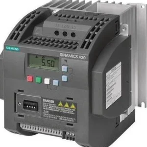 %68 Discount5.5 kW Variable Speed Drive - Siemens 380VOriginal price was: 1,342.30$.433.44$Current price is: 433.44$.View
Reviews
There are no reviews yet.