
No products in the cart.
%60 Discount


2.2 kW 220V Motor Drive Inverter
Original price was: 272.02$.108.80$Current price is: 108.80$.
High-performance industrial automation component for precise motor speed, torque, and direction control.
In stock
🔥 Special for Today Only %60 Discount Opportunity!📦 Category: 2.2 kW Speed Control Devices🏷️ Power: 2.2 kW🏷️ Supply Voltage: 220V
Mermak assuranceFrom factory to end user · importer / main dealer · strong stock
ImporterMain dealer / distributorStrong stockGood priceCorporate invoice
In stock / available to order · 14-day return for standard unused products; conditions may vary for custom size/cut products.
2.2 kW 220V Motor Drive Inverter
INDUSTRIAL AUTOMATION PARTS | SUPERIOR PERFORMANCE SERIES
Detailed Product Review
The K10-2S02R2G model Motor Drive Inverter, offered by Mermak CNC Technology Market, is a power electronics device designed to control the speed, torque, and direction of alternating current (AC) motors. Its primary function is to take a standard 220V AC single-phase mains voltage, convert it to direct current (DC) via an internal rectifier circuit, store this DC voltage on a DC bus (DC Link), and finally convert it into a variable amplitude and variable frequency three-phase (trifaze) AC voltage using an inverter bridge (typically IGBT-based). This conversion process precisely adjusts the voltage and frequency applied to the stator windings of the connected 2.2 kW three-phase asynchronous motor, allowing control over the motor’s synchronous speed and thus its rotor speed. Equipped with a Sensorless Vector Control (SVC) algorithm, it enables independent control of the motor’s magnetic flux and torque components. This results in high starting torque even at low speeds and stable speed regulation, a critical advantage for applications requiring high precision and dynamic response, such as CNC router spindle motors.
The internal structure of the device is designed to optimize high power density and thermal management. Power electronic components (IGBT modules, diodes) are typically mounted on aluminum heatsinks, with an integrated fan system providing active cooling to maintain operating temperatures and ensure long-lasting performance. The control board is based on a DSP (Digital Signal Processor) or microcontroller, executing motor control algorithms (SVC, V/F) while simultaneously monitoring various protection functions (overcurrent, overvoltage, undervoltage, overload, over-temperature, short circuit) in real-time, protecting the motor and drive from potential damage. With its compact dimensions (approx. 175x125x135 mm) and user-friendly terminal layout, this inverter can be easily integrated into industrial automation panels or machine frames. Its single-phase input feature makes it an ideal solution for hobby workshops, small-scale manufacturing facilities, or semi-professional environments using domestic power grids where three-phase industrial electricity is not available. Application areas range widely from high-speed spindle motors in CNC routers and milling machines to benchtop lathes, band saws, conveyor systems, pump and fan applications, air compressors, and textile machinery, where precise control of motor speed and torque directly impacts processing quality, energy efficiency, and machine lifespan.
Advantages of the 2.2 kW 220V Motor Drive Inverter
Superior Dynamic Performance with Advanced Vector Control: This inverter utilizes an advanced sensorless vector control (SVC) algorithm to independently control the magnetic flux and torque-producing components of the motor’s stator current. This technique provides the ability to deliver a significant portion of the motor’s nominal torque, especially at low speeds, and responds quickly and stably to rapid changes in speed reference. For 2.2 kW motors, it achieves precise speed regulation and torque stability even at high speeds like 24,000 RPM, which is crucial for CNC router spindle motors concerning cutting depth and surface finish, as motor speed drops or vibrations directly affect machining accuracy.
High Resistance to Sudden Load Changes and Stability: The device’s control algorithms are optimized to detect sudden and unexpected changes in the load applied to the motor shaft in real-time. For instance, during a sudden increase in load when a cutting tool engages material in a CNC machine, the inverter instantly increases motor current to maintain motor speed and torque close to nominal values. This dynamic response capability prevents motor speed drops or stalls, ensuring uninterrupted processing. Compared to standard V/F control drives on the market, this inverter’s current and speed control loops provide a faster and more stable response to load variations, leading to consistent machining quality and increased operational efficiency.
Infrastructure Flexibility and Cost Advantage with Single-Phase Input to Three-Phase Output: This 2.2 kW inverter can operate from a 220V AC single-phase mains voltage and produce a 0-220V AC three-phase output voltage. This feature offers a critical advantage for hobby workshops, small businesses, or home-use areas where a three-phase industrial electrical infrastructure is unavailable or costly to install. Users can operate 2.2 kW three-phase motors at optimal performance without needing to modify their existing single-phase electrical systems. This reduces initial investment costs and provides electrical infrastructure flexibility, enabling the use of industrial-type motors across a wide range of applications. Furthermore, optimization algorithms that precisely adjust the power required by the motor minimize unnecessary energy consumption, leading to long-term operational cost savings.
Technical Specifications and Capacity
FeatureValue/Description
Model CodeK10-2S02R2G
Input Voltage220V AC Single-Phase
Output Power2.2 kW (3 HP)
Output Current9.5 A (Nominal Continuous)
Output Frequency0 – 400 Hz (Adjustable)
Control ModeSensorless Vector Control (SVC), V/F Control
Overload Capacity150% for 60 seconds, 180% for 2 seconds
Protection FunctionsOvercurrent, overvoltage, undervoltage, overload, over-temperature, short circuit
Technical Frequently Asked Questions (FAQ)
What are the main differences between the Sensorless Vector Control (SVC) and V/F Control modes in this inverter and their application areas?
V/F (Voltage/Frequency) control is the most basic control method that attempts to keep the motor’s magnetic flux approximately constant by maintaining a fixed ratio (V/Hz) between the motor’s stator voltage and frequency. This method is generally sufficient for applications like pumps and fans that require constant load and a wide speed range. However, torque production at low speeds is limited, and its dynamic response to load changes is poor. Sensorless Vector Control (SVC), on the other hand, separates the motor’s stator current into magnetic flux and torque components, controlling each independently. This more accurately models the motor’s internal dynamics, providing much higher starting torque and more stable speed regulation, especially at low speeds. It is called “sensorless” because it achieves this performance without needing a speed sensor attached to the motor shaft. For applications requiring high torque, precise speed control, and rapid response to sudden load changes, such as CNC router spindle motors, lathes, or conveyors, the SVC mode should be preferred, as it significantly enhances machining quality and efficiency.
What does the inverter’s 0-400 Hz output frequency range mean for motor performance and application flexibility?
The synchronous speed of an AC motor is directly related to the applied frequency and the motor’s number of poles (Ns = (120 * f) / P, where Ns is synchronous speed, f is frequency, and P is the number of poles). The wide output frequency range of 0-400 Hz for this inverter allows the connected three-phase motor to be operated significantly above or below its nominal frequency (typically 50 Hz or 60 Hz). The 0-50 Hz range provides precise speed control below the motor’s nominal speed, while the 50-400 Hz range allows operation at very high speeds, far exceeding the motor’s nominal speed. Especially for high-speed spindle motors used in CNC routers, reaching speeds like 24,000 RPM, this wide frequency range enables them to be utilized to their full potential. This flexibility allows the motor speed to be optimally adjusted for different machining speeds and material types, improving machining quality and extending tool life. Furthermore, the ability to control motors with different nominal frequencies using a single inverter increases application versatility.
How do the protection functions in this inverter ensure long-term and safe operation of the motor and drive?
The inverter is equipped with a comprehensive set of protection functions to safeguard the connected motor and itself from various electrical and thermal faults. Overcurrent protection cuts off the inverter’s output when a condition exceeding the nominal current value is detected (e.g., sudden overload or short circuit), preventing damage. Overvoltage and undervoltage protections safeguard the drive and motor from fluctuations outside acceptable limits in the mains voltage. Overload protection activates when the motor operates above its nominal load for an extended period, preventing overheating of the motor windings and insulation breakdown. Overtemperature protection shuts down the drive when the internal power electronic components (IGBTs) or heatsinks exceed critical temperature thresholds, preventing thermal damage. Short circuit protection reacts instantly to phase-to-phase or phase-to-ground short circuits in the motor output terminals or windings, protecting both the inverter and the motor from severe damage. These protection mechanisms are fundamental elements that guarantee the safe, stable, and long-term operation of the inverter and the connected motor.
When using a single-phase input inverter, how should the compatibility between the three-phase motor’s nominal power and the inverter’s output power be evaluated?
When driving a three-phase motor with a single-phase input inverter, the single-phase power drawn from the mains is converted to DC by the internal rectifier circuit. This DC bus voltage is then converted to a three-phase output. During this process, the current drawn from the single-phase mains can be higher than the current drawn by the three-phase motor, as the power (P=V*I*cosφ) is supplied from the single-phase side via one phase, while it is distributed via three phases on the three-phase side. Therefore, the inverter’s input current capacity and the mains line’s carrying capacity are critical. A 2.2 kW inverter is generally designed to drive a 2.2 kW three-phase motor at full power. However, with single-phase input inverters, instantaneous current draws can occur, especially during motor’s sudden startups or operation under high load. This necessitates proper sizing of the mains line and fuses. Additionally, the motor’s nominal voltage must be compatible with the inverter’s output voltage (220V in this case). As a general rule, the inverter’s nominal output power should be selected to be equal to or slightly higher than the nominal power of the motor to be driven. This ensures the motor operates at full performance while preventing the inverter from being overloaded and failing prematurely. The characteristics of the application (constant load, variable load, requirement for high starting torque) are also important factors in evaluating this compatibility.
| Power | 2.2 kW |
|---|---|
| Supply Voltage | 220V |
You must be logged in to post a review.
Taksit Tablosu
Related Products
 %42 Discount750W Servo Motor Set 80ST-M02430 T3L-L20F-RABNOriginal price was: 558.28$.323.21$Current price is: 323.21$.View
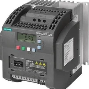 %68 Discount5.5 kW Variable Speed Drive - Siemens 380VOriginal price was: 1,342.30$.433.44$Current price is: 433.44$.View
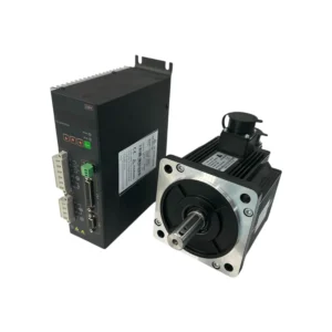 %40 Discount1.5 kW Servo Motor Set 130ST-M06025 T3A-L30F-RABFOriginal price was: 864.26$.520.38$Current price is: 520.38$.View
Reviews
There are no reviews yet.