No products in the cart.
How Timing Pulley Tooth Count Affects Speed and Torque
Contents
Discover how the number of teeth on a timing pulley directly impacts rotational speed and torque. This article explains the principles behind these changes and their critical role in industrial automation, including CNC machinery.
Mermak CNC Technical Guide
Practical notes for CNC router, automation and industrial motion systems.
Understanding the Impact of Timing Pulley Tooth Count on Speed and Torque
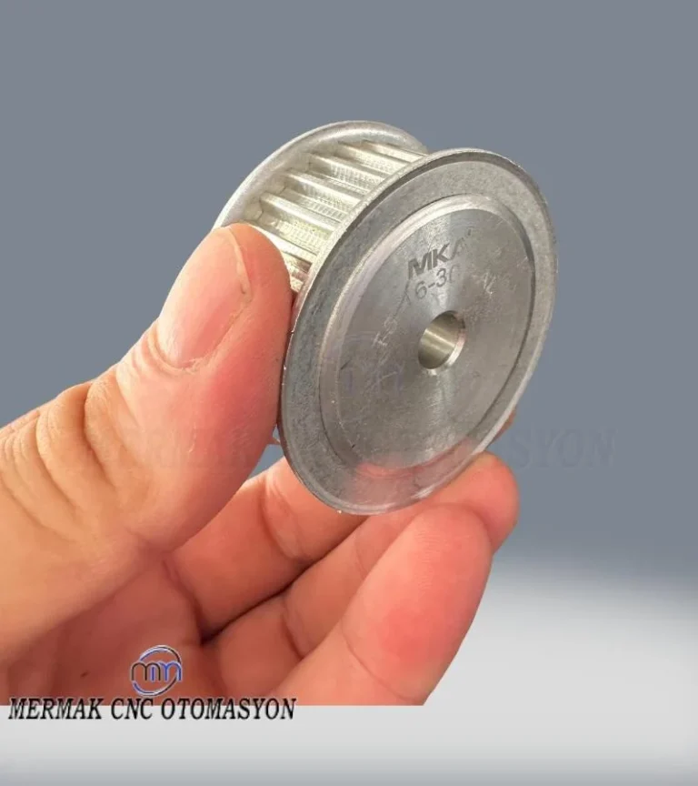
In industrial automation systems, particularly those requiring synchronized motion and precise positioning, timing pulleys and timing belts play a crucial role. The fundamental principle involves transferring motion from a driving pulley (motor shaft) to a driven pulley via a timing belt. Among the key parameters that directly influence speed and torque during this transfer is the number of teeth on the pulleys. This tooth count determines the overall gear ratio of the system, thereby directly modifying the output shaft’s speed and torque. This effect is a key factor in optimizing a system for specific applications; for instance, it differentiates a conveyor system requiring high torque at low speeds from a positioning system needing high speed with low torque. Engineers leverage this principle to transform a motor’s nominal speed and torque characteristics to best suit application requirements.
Operating Principle and Technical Data
Power transmission in timing pulleys occurs through the precise meshing of the belt’s teeth with the pulley’s grooves, ensuring slip-free operation and synchronization. This synchronization is essential for precise motion control. To understand how speed and torque are affected by tooth count, we examine the ratio between the driving (input) and driven (output) pulleys’ teeth.

Effect on Speed
Speed is dependent on the ratio between the number of teeth on the driving pulley (Z_drive) and the driven pulley (Z_driven). The general formula is:
N_driven = N_drive * (Z_drive / Z_driven)
Where N represents rotational speed (typically RPM – revolutions per minute).
- Z_driven > Z_drive (Driven pulley is larger): In this case, the ratio is less than 1, meaning the driven pulley’s speed (N_driven) will be lower than the driving pulley’s speed (N_drive). This is a speed reduction system. For example, if the drive pulley has 20 teeth and the driven pulley has 40 teeth, the driven pulley will rotate at half the speed.
- Z_driven < Z_drive (Driven pulley is smaller): Here, the ratio is greater than 1, resulting in the driven pulley’s speed (N_driven) being higher than the driving pulley’s speed (N_drive). This is a speed increase system. For example, if the drive pulley has 40 teeth and the driven pulley has 20 teeth, the driven pulley will rotate at double the speed.
- Z_driven = Z_drive (Equal tooth count): Both pulleys will rotate at the same speed (1:1 ratio).

Effect on Torque
Torque is inversely proportional to speed (ignoring system efficiency). Assuming constant power input, a decrease in speed leads to an increase in torque, and vice versa. The general formula for torque (including efficiency) is:
T_driven = T_drive * (Z_driven / Z_drive) * Efficiency
Where T represents torque, and Efficiency accounts for energy losses in the belt and pulley system (friction, elasticity, etc.), typically between 0.95-0.98.
- Z_driven > Z_drive (Driven pulley is larger): The ratio is greater than 1, so the torque at the driven pulley (T_driven) will be higher than at the driving pulley (T_drive). This is a torque increase system, occurring simultaneously with speed reduction.
- Z_driven < Z_drive (Driven pulley is smaller): The ratio is less than 1, so the torque at the driven pulley (T_driven) will be lower than at the driving pulley (T_drive). This is a torque reduction system, occurring simultaneously with speed increase.
These principles are vital across many industrial automation sectors. For instance, when a robotic arm needs to lift heavy loads, a pulley combination is chosen to reduce speed and increase torque. A high-speed labeling machine might use a combination that reduces torque while increasing speed. Selecting the correct tooth count ensures efficient motor operation, prevents overload, and extends system lifespan.
| Parameter | Value/Description |
|---|---|
| Gear Ratio (i) | i = Z_driven / Z_drive |
| Speed Effect (N_driven) | N_drive / i (Speed decreases if i > 1, increases if i < 1) |
| Torque Effect (T_driven) | T_drive * i * Efficiency (Torque increases if i > 1, decreases if i < 1) |
| Power Transmission | Constant excluding efficiency (P = T * N); unaffected by pulley ratio. |
| Precision | Increased tooth count can enhance precision, as each tooth movement corresponds to a smaller angular displacement. |
| Vibration and Noise | Correct tooth profile and ratio selection minimize vibration and noise. Incorrect choices can increase them. |
| Application Areas | CNC machines, robotic arms, conveyor systems, packaging machinery, textile machinery. |

Field Considerations
- Tooth Profile and Belt Compatibility: Timing pulleys and belts have specific tooth profiles (e.g., HTD, GT, T, AT). Ensuring 100% compatibility between the pulley and belt tooth profile is critical. Using the wrong profile can lead to belt tooth skipping, excessive wear, noise, and reduced efficiency, causing significant errors in systems requiring precise positioning, especially those with servo motors. Always use manufacturer-recommended profiles and dimensions for your projects.
- Tension Adjustment: Proper timing belt tension is vital for system performance and longevity. Over-tensioning places undue load on bearings, shortens belt life, and increases system friction losses. Insufficient tension can cause belt tooth skipping, vibration, and power transmission losses. Belt tension should be adjusted according to manufacturer instructions, using specialized tension gauges or frequency analyzers.
- Material Selection: Pulley and belt materials must be chosen based on the application’s load, speed, temperature, and environmental conditions. Aluminum pulleys are lightweight and economical, while steel pulleys offer higher load and impact resistance. Stainless steel or plastic (polyacetal, nylon) pulleys may be suitable for specific applications. Belt materials (neoprene, polyurethane) should be selected based on resistance to oil, chemicals, and temperature.
- Assembly and Alignment: Correct alignment of pulleys and shafts is crucial for system efficiency and lifespan. Misalignment can cause excessive wear on belt edges, deformation of pulley flanges, uneven bearing loads, and increased noise. Check pulley parallelism and axial alignment using laser alignment tools or precision gauges.
- Environmental Conditions and Protection: Timing systems operating in dusty, humid, corrosive, or high-temperature environments may require special protective measures. Selecting materials resistant to these conditions or implementing protective enclosures is recommended.
Optimizing your CNC router machine or any industrial automation setup involves careful consideration of these factors. For expert advice and solutions tailored to your needs, request a quote on WhatsApp today.
Related product categories: Genel · 16 Mm Triger Dişli Kasnak · 16 mm Triger Dişli Kasnak