



































































































































Understanding Sensor Cables: Selecting the Right PNP, NPN, and Encoder Cables
📑 Table of contents (Click to open)
Sensor cables are vital for transmitting signals and power in industrial automation. This guide explains how to choose the right cables for PNP, NPN, and encoder systems, focusing on signal integrity, noise immunity, and durability in demanding environments.
Practical notes for CNC router, automation and industrial motion systems.
What is a Sensor Cable? Selecting for PNP, NPN, and Encoder Lines
In industrial automation, sensors are the eyes and ears, detecting physical conditions like position, temperature, and pressure, and converting them into electrical signals. The reliable transmission of these signals to control systems (PLCs, DCS) is handled by specialized components known as sensor cables. More than just conductors, sensor cables are engineered to maintain signal integrity, resist electromagnetic interference (EMI), and withstand harsh industrial conditions. Choosing the appropriate sensor cable is crucial for overall system performance, stability, and longevity. Incorrect cable selection can lead to signal loss, erroneous readings, system failures, and costly production downtime. Therefore, understanding and implementing cable solutions tailored to specific needs, such as those for PNP, NPN, and encoder signals, requires expertise.
Operating Principles and Technical Data
The fundamental principle behind sensor cables is to carry electrical signals with minimal loss and maximum protection from external influences. However, not all sensors and applications are the same. Cable selection differs significantly for PNP (Positive-Negative-Positive) and NPN (Negative-Positive-Negative) sensors, as well as for encoder lines. These differences stem from sensor output types, signal frequencies, and environmental factors.
PNP and NPN Sensor Cables
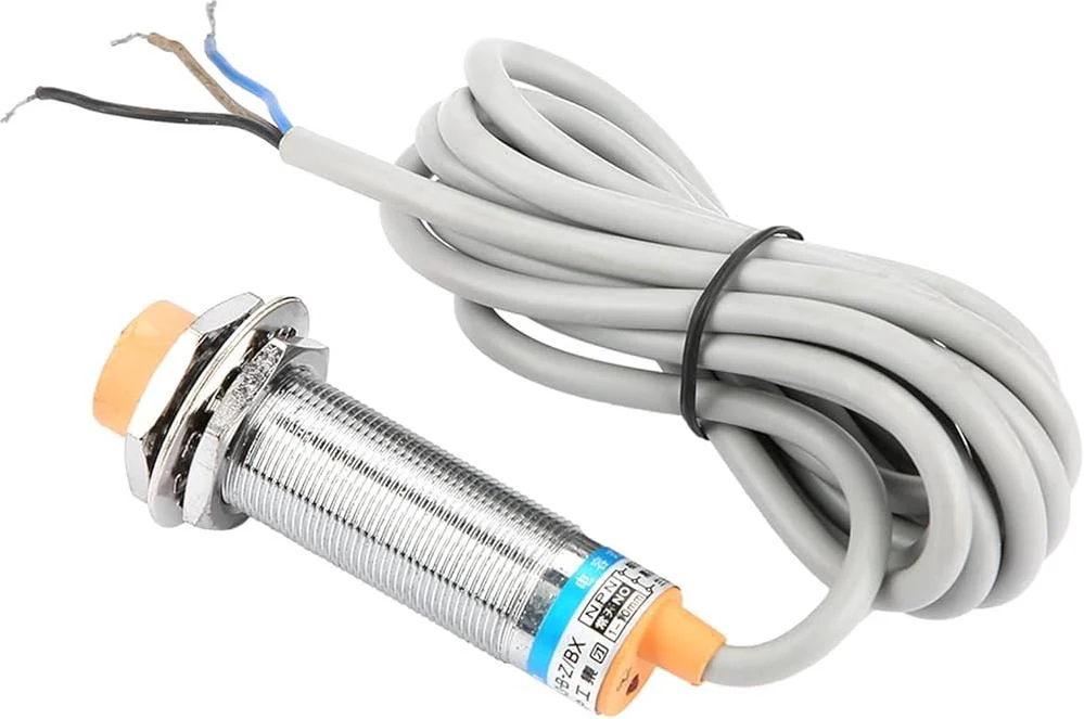
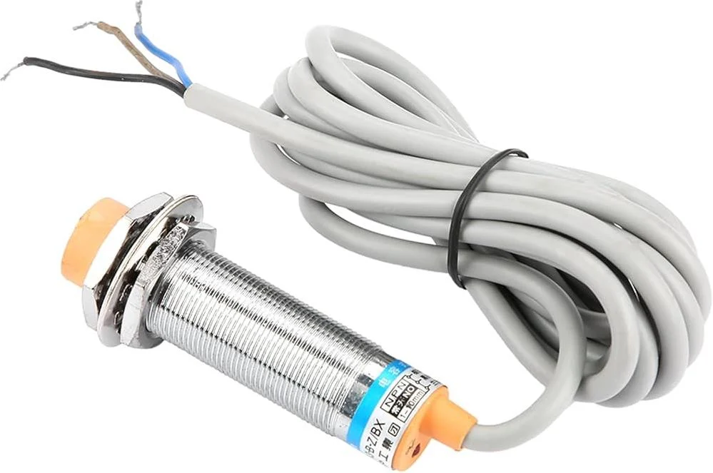
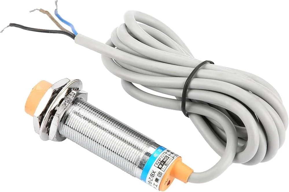
PNP sensors provide a positive voltage output (sourcing), while NPN sensors provide a negative voltage or ground connection (sinking). Both typically use a 3-wire connection: power (often brown), ground (often blue), and signal (often black). Some advanced sensors may include a fourth wire (white) for an auxiliary output or programming. These sensor cables commonly feature conductor cross-sections ranging from 0.25 mm² to 0.75 mm². As they carry low-frequency (DC) signals, their shielding requirements are generally less stringent. However, shielded cables are advisable for long distances or environments with high electromagnetic noise. Jacket materials like PVC or PUR offer protection against industrial oils, abrasion, and chemicals. PUR jackets are particularly suitable for applications demanding high flexibility and chemical resistance.
Cable Selection for Encoder Lines
Encoders are devices that convert rotational or linear motion into electrical signals, typically high-frequency pulses carrying precise position and speed data. Maintaining signal integrity and immunity to external noise is critical for encoder cables. Encoders often require 4, 6, 8, or more conductors. Basic encoders need conductors for A, B, and Z (index) phases, plus power and ground. Encoders with differential outputs (e.g., RS-422) use pairs for each signal (A/A’, B/B’, Z/Z’), increasing the conductor count. Differential signals offer superior noise immunity, making them ideal for long-distance applications. Shielding is essential for encoder cables, usually employing a combination of braid and foil for maximum noise absorption and signal quality. Differential signal lines are typically configured as twisted pairs, which further cancels out common-mode noise. PUR or TPE (Thermoplastic Elastomer) jackets are preferred for their high flexibility, abrasion resistance, and wide operating temperature range. For dynamic applications like robotics or cable carriers, specialized high-flexibility “robotic cables” are necessary.
| Parameter | Value/Description |
|---|---|
| Cable Type (PNP/NPN) | 3 or 4 Conductor DC Signal Cable |
| Cable Type (Encoder) | 4, 6, 8+ Conductor High-Frequency Signal Cable (Twisted Pair for Differential) |
| Number of Conductors | PNP/NPN: 3-4; Encoder: 4-12 (varies by application and signal type) |
| Conductor Cross-Section | 0.14 mm² – 0.75 mm² (typically 0.25 mm² – 0.34 mm²) |
| Shielding | PNP/NPN: Generally not required, foil for long distances; Encoder: Mandatory braid and/or foil (double shielding preferred) |
| Jacket Material | PVC (general), PUR (oil, abrasion, flexibility), TPE (high flexibility, temperature) |
| Operating Temperature | -40°C to +80°C (material dependent) |
| Application Area | Fixed installation, moving applications (cable carriers, robotics), harsh environments |
Field Considerations for Optimal Selection
- Environmental Conditions and Mechanical Stress: Assess the operating temperature range, humidity, chemical exposure (oils, acids, solvents), UV resistance, and mechanical demands (vibration, bending, abrasion). For instance, an encoder cable on a continuously moving robot arm requires high-flexibility, abrasion-resistant PUR or TPE robotic cables. Standard PVC cables might suffice for static installations.
- Signal Integrity and Noise Immunity: For long cable runs, high-frequency signals (encoders), or areas with significant EMI sources (motors, power lines), preserving signal integrity is paramount. Opt for shielded cables (foil, braid, or both) and ensure proper grounding. Twisted pairs in differential encoder lines minimize common-mode noise. Separating power and signal cables in different conduits also helps reduce interference.
- Conductor Count and Cross-Section: The sensor or encoder’s pinout and power requirements dictate the number of conductors. A simple 3-wire PNP sensor needs a 3-conductor cable, while a differential encoder with an index signal might require 8 or 10 conductors. Conductor cross-section is determined by cable length and current load to prevent voltage drop over long distances.
- Connector Compatibility and Ease of Installation: Ensure the cable connectors (M8, M12, M23, D-Sub, etc.) match the sensor and control unit. Pre-terminated cables reduce installation time and connection errors. Consider the cable’s bend radius and diameter relative to available space.
- Standardization and Compliance: Adhere to relevant industry standards (e.g., UL, CE, RoHS) for safety and performance. Using cables designed for specific applications, like drag-chain or robot applications, ensures reliability in demanding dynamic scenarios.
Conclusion
Selecting the correct sensor cable is a critical step in designing and maintaining reliable industrial automation systems. By carefully considering the sensor type (PNP, NPN, encoder), signal characteristics, environmental conditions, and mechanical stresses, you can choose cables that ensure optimal performance, signal integrity, and system longevity. Investing in the right cable solution prevents costly downtime and ensures the smooth operation of your CNC machinery and other automated processes.
Ready to ensure your automation systems are connected reliably? Request a quote on WhatsApp for expert advice and high-quality sensor cables tailored to your industrial needs.
Related product categories: Uncategorized · ssss3 · 0.75 Kw أجهزة التحكم في السرعة
