No products in the cart.
Rack and Pinion Gear Systems: Advantages and Disadvantages

Contents
- Rack and Pinion Gear Systems: Advantages and Disadvantages – Introduction and Technical Analysis At the heart of industrial automation, motion control systems are critical components that directly impact the efficiency, speed, and precision of modern manufacturing processes. Among these systems, rack and pinion gear systems, used to convert rotary motion into linear motion, play an indispensable role across a wide range of applications. These mechanisms are particularly preferred in long-distance and high-precision linear motion applications, finding their place in material handling systems, CNC machines, robotic applications, and precise positioning platforms. This field guide and technical article thoroughly covers the fundamental operating principles of rack and pinion systems, their advantages, encountered disadvantages, critical points to consider in the field, and solution proposals for common problems for industrial automation professionals. Our goal is to enable engineers and technicians to better understand these systems, make correct selections, and achieve optimized performance in their existing applications. Factors such as the mechanical strength, positioning accuracy, service life, and cost-effectiveness of the systems are of great importance for the success of any automation project, and this guide will provide an in-depth perspective on these issues. Rack and Pinion Gear Systems: Advantages and Disadvantages – Working Principle and Technical Data
- Rack and Pinion Gear Systems: Advantages and Disadvantages – Field Considerations
- Rack and Pinion Gear Systems: Advantages and Disadvantages – Common Problems and Solutions
- Rack and Pinion Gear Systems: Advantages and Disadvantages – Conclusion and Expert Advice
- FAQ
Rack and Pinion Gear Systems: Advantages and Disadvantages – Introduction and Technical Analysis
At the heart of industrial automation, motion control systems are critical components that directly impact the efficiency, speed, and precision of modern manufacturing processes. Among these systems, rack and pinion gear systems, used to convert rotary motion into linear motion, play an indispensable role across a wide range of applications. These mechanisms are particularly preferred in long-distance and high-precision linear motion applications, finding their place in material handling systems, CNC machines, robotic applications, and precise positioning platforms. This field guide and technical article thoroughly covers the fundamental operating principles of rack and pinion systems, their advantages, encountered disadvantages, critical points to consider in the field, and solution proposals for common problems for industrial automation professionals. Our goal is to enable engineers and technicians to better understand these systems, make correct selections, and achieve optimized performance in their existing applications. Factors such as the mechanical strength, positioning accuracy, service life, and cost-effectiveness of the systems are of great importance for the success of any automation project, and this guide will provide an in-depth perspective on these issues.
Rack and Pinion Gear Systems: Advantages and Disadvantages – Working Principle and Technical Data
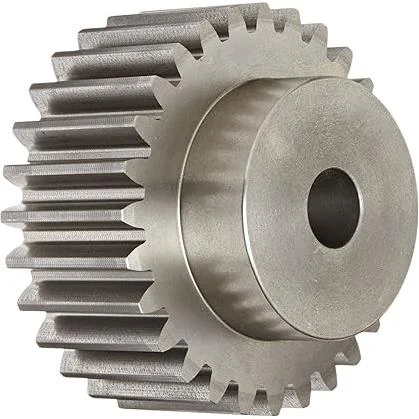
A rack and pinion gear system fundamentally consists of two main components: the rack, which has teeth machined onto a linear bar, and the pinion, a small, circular gear that meshes with the rack’s teeth and moves it linearly through rotational motion. When the pinion is rotated by an electric motor or another actuator, it moves the rack forward or backward a specific linear distance, depending on the gear ratio and the pinion’s diameter. This simple yet effective mechanism is one of the most direct ways to convert rotational energy into linear force. The system’s accuracy and repeatability performance are directly dependent on the manufacturing quality of the gears, assembly precision, and the materials used. Generally, high-quality, ground gears are preferred for precise applications, while milled or cast gears may suffice for less critical applications. Rack and pinion gear systems are ideal for long stroke lengths, as the size of the rack can theoretically be extended indefinitely. This provides them with certain advantages over other linear actuators such as ball screws or belt-driven systems.
Advantages:
- Long Stroke Lengths: Racks can be combined in a modular structure or as a single piece to provide linear motion over very long distances. This is a critical feature for material handling lines and large-scale robotic systems.
- High Speed Capacity: Thanks to low friction and high rigidity, rack and pinion systems can achieve high linear speeds, which shortens production cycle times.
- High Load Capacity: Gear contact distributes the load over a wide area, allowing it to carry high radial and axial loads. This is important in applications such as heavy machinery and press systems.
- High Rigidity and Precision: Especially when helical racks and precision ground pinions are used, systems offer high positioning accuracy and repeatability with minimal backlash. Anti-backlash pinions further enhance this precision.
- Easy Maintenance: Due to their relatively simple structure and open design, visual inspection and lubrication operations can be easily performed.
- Cost-Effectiveness: Especially considering long stroke lengths, they can offer a more cost-effective solution compared to other precise linear motion systems like ball screws.
Disadvantages:
- Backlash: The unavoidable clearance between gears can cause positioning errors, especially during direction changes. In precise applications, this should be minimized with anti-backlash pinions or dual pinion systems, but this also increases cost.
- Assembly Precision: Correct alignment of the rack and pinion, parallel mounting, and adjustment of the gear mesh depth are critically important. Incorrect assembly leads to premature wear, noise, and loss of precision.
- Noise and Vibration: Especially in straight tooth racks, impact sounds generated during gear contact can cause noise and vibration. Helical gears significantly reduce this.
- Environmental Sensitivity: Exposed gears can be easily affected by dust, dirt, chips, and abrasive particles. This requires regular cleaning and protection; otherwise, wear accelerates.
- Efficiency: Due to losses from friction and gear contact, energy efficiency may be slightly lower compared to some other linear motion systems.
Technical Data and Engineering Parameters:
- Module (m): The fundamental parameter defining tooth size. The module of the rack and pinion must be the same. As the module increases, teeth get larger, load capacity increases, but speed decreases.
- Pressure Angle: Determines the direction of force transmission of the gears. Typically 20 degrees is used.
- Material: High-carbon steels (C45, 42CrMo4), stainless steels, and some special alloys are preferred. Surface hardening (induction, carburizing) increases wear resistance.
- Precision Class: According to DIN or ISO standards (e.g., DIN 7, DIN 6). As the class number decreases, precision increases.
- Linear Speed: Linear speed (m/s) obtained depending on the pinion’s RPM and pitch diameter.
- Load Capacity: Varies depending on gear strength, material, module, and pinion diameter.
- Backlash: The amount of free play between gears. Critical in applications requiring micron-level precision.
| Parameter | Value/Description |
|---|---|
| Module (m) | 0.5 to 16+ (Varies by application, ratio of tooth size in mm) |
| Precision Class | DIN 5 (Very High) – DIN 10 (Low). DIN 6 or DIN 7 is generally preferred. |
| Material Type | C45 (1.0503), 42CrMo4 (1.7225), Stainless Steels. Surface hardening (induction) is common. |
| Linear Speed Capacity | From 1 m/s to 10 m/s (Depends on system rigidity and pinion RPM). |
| Backlash | Standard: 50-100 microns. Precision: 0-20 microns (with anti-backlash systems). |
| Load Capacity | From a few hundred N to several kN (Depends on module, material, gear type, and contact area). |
| Rack Length | Single piece 0.5m – 3m. Theoretically unlimited with joining. |
| Tooth Type | Spur or Helical. Helical is quieter and has higher load capacity. |
Rack and Pinion Gear Systems: Advantages and Disadvantages – Field Considerations
- Assembly and Alignment Precision: The performance of rack and pinion systems is directly related to correct assembly and alignment. The mounting surface of the rack must be perfectly flat and parallel to the pinion’s axis of motion. Any angular or parallel deviation will lead to irregular gear contact, premature wear, noise, and increased backlash. During assembly, special alignment tools and precise measurement equipment should be used, and the gear mesh depth (center distance) adjustment must be meticulously performed according to manufacturer specifications. Incorrect alignment significantly shortens the system’s lifespan and can lead to unexpected failures.
- Lubrication and Maintenance Schedule: Gear systems cannot operate efficiently without continuous and proper lubrication. Insufficient lubrication leads to excessive friction, heating, and rapid wear of the gears. Industrial gear oils or greases of the appropriate type and viscosity should be selected according to operating conditions (load, speed, temperature, environment). Automatic lubrication systems ensure optimal lubrication by minimizing human error, especially in harsh environments or applications requiring continuous operation. Periodic inspection and lubrication schedules should be meticulously followed according to manufacturer recommendations, and oil levels and quality should be regularly checked.
- Backlash Management: Backlash is an unavoidable clearance between gears and can cause positioning errors, especially during direction changes. In applications requiring precise positioning, this backlash can pose a critical problem. As a solution, precision ground gears, adjustable backlash systems, or anti-backlash pinions (preloaded dual pinions) can be used. These systems minimize the clearance between gears, increasing positioning accuracy. However, anti-backlash systems are generally more costly and have a more complex design, so the precision requirements of the application must be well analyzed.
- Environmental Protection and Sealing: Rack and pinion gears are exposed mechanisms and are therefore quite sensitive to environmental factors. Dust, dirt, metal chips, moisture, and abrasive chemicals can accumulate on gear surfaces, accelerating wear and degrading the lubrication film. Therefore, especially in industrial environments, proper protection of the gears is vital. The system must be isolated from external factors using protective bellows, covers, wipers, and special sealing elements. The ingress of abrasive particles between the gears can lead to serious damage known as “third-body wear.”
- Material Selection and Heat Treatment: The material and heat treatment of the rack and pinion directly affect the system’s load-carrying capacity, wear resistance, and lifespan. For systems operating under high torque and impact loads, hardened steels (e.g., induction-hardened 42CrMo4) or carburizing steels should be preferred. Stainless steels are suitable for humid or chemical environments where corrosion resistance is important. Material selection should be made considering the mechanical properties required by the application, environmental conditions, and cost factors. Incorrect material selection can lead to premature fatigue or tooth breakage.
- System Rigidity and Vibration Control: Ensuring sufficient rigidity throughout the mechanical system is important to minimize vibrations and resonance. The chassis on which the rack is mounted, and the motor and gearbox assembly driving the pinion must have sufficient rigidity. Vibrations can reduce system precision, increase noise, and cause fatigue damage to components. Helical racks provide smoother contact than straight teeth, making them more effective in reducing noise and vibration. Additionally, the vibration characteristics of the system can be improved by using appropriate damping elements and dynamic balancing techniques.
Rack and Pinion Gear Systems: Advantages and Disadvantages – Common Problems and Solutions
Problems encountered in rack and pinion systems in industrial automation applications typically manifest as symptoms such as mechanical wear, positioning errors, noise, and vibration. Understanding the root cause of these problems and implementing correct solutions is critical to extending system life and ensuring production efficiency.
1. Excessive Backlash and Positioning Errors:
- Problem: Unwanted movement or a decrease in positioning accuracy during system direction changes. This negatively affects product quality, especially in precise machining or assembly operations.
- Causes:
- Wear on gears (insufficient lubrication, excessive load, abrasive environment).
- Incorrect gear mesh depth (center distance) adjustment.
- Loose assembly or insufficient system rigidity.
- Play in the mounting bearings of the pinion or rack.
- Solutions:
- Readjust the gear mesh depth (center distance) according to manufacturer recommendations. Adjustable pinion housings or eccentric bushings can be used.
- Replace worn gears or bearings.
- For precise applications, use anti-backlash pinions or dual pinion systems. These systems apply preload to eliminate gear backlash.
- Check and tighten mounting bolts; increase the overall rigidity of the system.
2. Excessive Noise and Vibration:
- Problem: High noise levels and/or noticeable vibrations during operation. This reduces operator comfort, can cause fatigue, and damage other components.
- Causes:
- Incorrect alignment or lack of parallelism.
- Insufficient or incorrect lubrication.
- Worn or damaged gears (burrs, broken teeth).
- Excessive load or high speed.
- Use of spur gears (noisier than helical gears).
- Resonance in the system or loose assembly.
- Solutions:
- Precisely check and adjust the alignment and parallelism of the rack and pinion.
- Ensure correct type and amount of lubrication.
- Replace damaged gears.
- Consider using helical rack and pinion instead of spur gears. Helical gears provide smoother contact, significantly reducing noise.
- Review the system’s mounting points and overall rigidity, tighten loose connections.
- Use vibration dampeners if necessary.
3. Gear Wear and Breakage:
- Problem: Material loss on tooth surfaces (pitting, scoring, spalling) or tooth breakage. This shortens the system’s lifespan and can lead to sudden failures.
- Causes:
- Insufficient or inappropriate lubrication.
- Excessive load or sudden impact loads.
- Ingress of abrasive particles (dust, dirt, chips) between the gears.
- Insufficient material hardness or incorrect heat treatment.
- Incorrect tooth profile or manufacturing defect.
- Stresses caused by thermal expansion differences.
- Solutions:
- Implement a correct lubrication schedule and use an appropriate, high-performance lubricant. Protect gears from environmental contaminants (bellows, covers).
- Ensure the system does not exceed its load capacity. If necessary, use gears with a larger module or made from more durable material.
- Keep the operating environment clean and enclose gears with protective barriers.
- Check material and heat treatment specifications. Use surface-hardened gears with high wear resistance.
- Consider thermal expansion clearances in assembly, especially for long racks.
4. Irregular or Stick-Slip Motion:
- Problem: The rack moves unevenly, sticking, or intermittently. This becomes pronounced at low speeds and makes precise control difficult.
- Causes:
- Insufficient or inappropriate lubrication (increased friction coefficient).
- Corrosion or rusting on rack or pinion surfaces.
- Unevenness or contamination on mounting surfaces.
- Problems with the pinion’s drive motor or gearbox.
- Excessive friction in bearings or linear guides.
- Solutions:
- Check the lubrication system and use an appropriate, high-performance lubricant.
- Clean gear surfaces and remove any rust or corrosion.
- Ensure the rack’s mounting surfaces are smooth and clean.
- Verify that the drive motor and gearbox are operating correctly.
- Check the pinion’s bearings and the linear guides supporting the rack; clean or replace if necessary.
Rack and Pinion Gear Systems: Advantages and Disadvantages – Conclusion and Expert Advice
Rack and pinion gear systems are a critical cornerstone in providing linear motion in industrial automation. With their long stroke capacity, high-speed potential, and load-carrying capability, they are indispensable in many applications. However, to fully utilize the potential of these systems and ensure long-lasting, trouble-free operation, the care shown in the design, selection, assembly, and maintenance processes is of vital importance. As an automation expert, based on my field experience, I can clearly state that the success of rack and pinion systems lies in “attention to detail.” Technical parameters such as module selection, gear type (straight or helical), precision class, material, and heat treatment must precisely match the application’s requirements, directly affecting both the system’s performance and cost-effectiveness. Especially in applications requiring high dynamics or precision, investing in advanced solutions like anti-backlash pinions or dual pinion systems for backlash management, although increasing initial cost, will pay for itself in the long run by reducing downtime and maintenance costs. Furthermore, environmental protection and regular, correct lubrication are the most fundamental ways to extend the system’s life and prevent unexpected failures. The care shown in the installation of a system determines its efficiency and reliability in the operational process. Meticulous alignment, gear mesh depth adjustment, and the use of appropriate tightening torques during assembly prevent many problems that may be encountered after initial startup. In conclusion, rack and pinion systems, with the right engineering approaches and careful maintenance, will continue to be one of the most reliable and efficient linear motion solutions in industrial automation. When evaluating these systems for your future automation projects, focusing not only on their advantages but also on their potential disadvantages and how they can be managed will lead you to success.
FAQ
How do rack and pinion gear systems work?
Rack and pinion systems convert rotary motion into linear motion. A rotating pinion gear meshes with a linear rack, causing the rack to move in a straight line. This mechanism is widely used for precise and powerful linear movement in industrial applications.
What are the main advantages of using rack and pinion systems?
Key advantages include long stroke capabilities, high linear speeds, high load capacity, and good rigidity for precise positioning. They are also relatively cost-effective for long travel distances compared to other linear motion solutions.
What are the common disadvantages of rack and pinion systems?
Disadvantages can include backlash (play between gears), which affects precision, and susceptibility to environmental contaminants like dust and chips due to exposed gears. They can also generate more noise and vibration than helical gear systems.
What should be considered during the installation and maintenance of rack and pinion systems?
Critical factors include precise mounting and alignment, consistent and appropriate lubrication, effective backlash management (e.g., using anti-backlash pinions), environmental protection, correct material selection with suitable heat treatment, and ensuring overall system rigidity to minimize vibration.
What are the typical problems encountered with rack and pinion systems and how can they be solved?
Common issues include excessive backlash leading to positioning errors, high noise and vibration, premature gear wear or breakage, and irregular 'stick-slip' motion. Solutions involve proper alignment, lubrication, using helical or anti-backlash gears, and environmental shielding.