
No products in the cart.
How to Select a Stepper Motor for Rack and Pinion Systems

Contents
- Introduction and Technical Analysis In industrial automation systems, precise positioning, high repeatability, and reliable motion control are critical for the efficiency and quality of manufacturing processes. In this context, rack and pinion systems are frequently preferred mechanical solutions for long-distance linear motion requirements. These systems, which convert rotary motion into linear motion, are used in a wide range of applications such as material handling, CNC router machines, robotic arms, and automation lines. For driving rack and pinion systems, stepper motors stand out as a popular option due to their cost-effectiveness, simple control mechanism, and high precision potential. However, selecting the correct stepper motor for a rack and pinion system is a comprehensive process that requires much more than just looking at the motor’s torque values; it demands engineering discipline and field experience. This guide aims to provide industrial automation professionals with the technical parameters, calculation methods, and practical tips to consider when selecting a stepper motor, ensuring optimal system performance and longevity. Operating Principle and Technical Data
- Field Considerations
- Common Problems and Solutions
- Expert Advice
- FAQ
Introduction and Technical Analysis
In industrial automation systems, precise positioning, high repeatability, and reliable motion control are critical for the efficiency and quality of manufacturing processes. In this context, rack and pinion systems are frequently preferred mechanical solutions for long-distance linear motion requirements. These systems, which convert rotary motion into linear motion, are used in a wide range of applications such as material handling, CNC router machines, robotic arms, and automation lines. For driving rack and pinion systems, stepper motors stand out as a popular option due to their cost-effectiveness, simple control mechanism, and high precision potential. However, selecting the correct stepper motor for a rack and pinion system is a comprehensive process that requires much more than just looking at the motor’s torque values; it demands engineering discipline and field experience. This guide aims to provide industrial automation professionals with the technical parameters, calculation methods, and practical tips to consider when selecting a stepper motor, ensuring optimal system performance and longevity.
Operating Principle and Technical Data
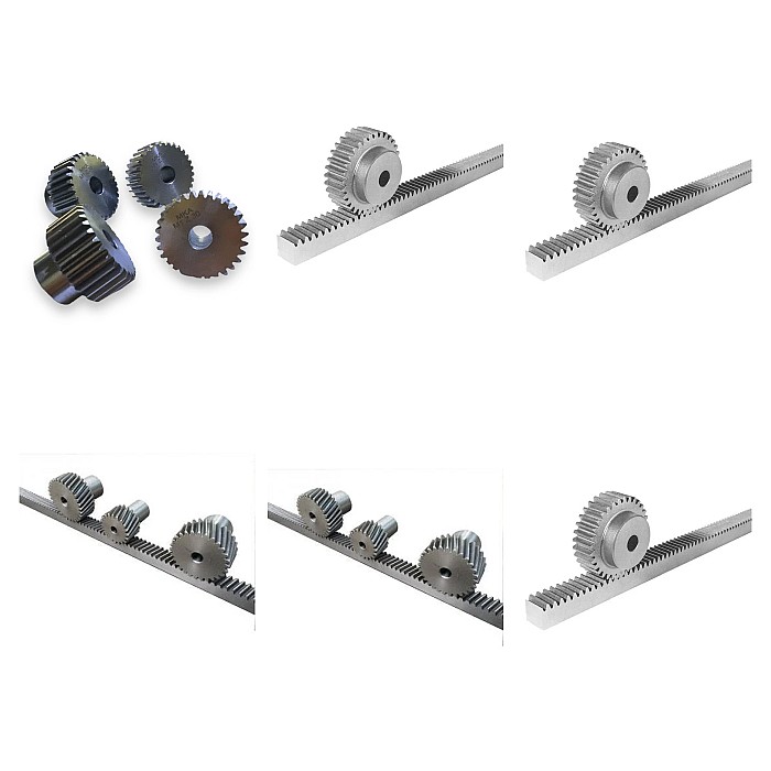
A rack and pinion system consists of two main components: a circular gear (pinion) and a linear gear (rack) with teeth along a straight line. As the pinion rotates, linear motion occurs along the rack. The main advantages of this system include long stroke capability, high rigidity, and high load-carrying capacity. Stepper motors, on the other hand, are motors with open-loop or closed-loop control capability that convert electrical pulses into mechanical rotational steps. Each electrical pulse causes the motor to rotate at a specific angle, enabling very precise positioning. When a stepper motor drives a rack and pinion system, the motor’s rotational motion is transmitted to the rack via the pinion. In this conversion, the motor’s torque, speed, and precision directly affect the overall system performance.
The main technical data and calculations to consider for selecting the correct stepper motor are as follows:
-
Torque Requirement (Load Torque): The sum of all friction forces (rack-pinion, bearings, guides), acceleration/deceleration forces, and forces resulting from external loads in the system must be calculated.
- Friction Torque (Tfriction): Includes losses such as friction between the rack and pinion, friction in bearings, and friction in guides. These values are typically determined by experimental data or manufacturer specifications.
- Acceleration Torque (Tacceleration): The torque required for the system to move with a specific acceleration. It is calculated using the mass of the load (m), the radius of the pinion (r), and the desired linear acceleration (a): Tacceleration = (m * a * r) + (Jmotor + Jpinion + Jload_converted) * α. Here, J represents the moments of inertia, and α represents the angular acceleration.
- External Load Torque (Tload): Forces that directly act on the motor, such as vertically moving loads or cutting forces. Calculated as Fload * r.
- Total Torque (Ttotal): Ttotal = Tfriction + Tacceleration + Tload. The holding torque of the selected motor should be at least 20-50% higher than this total torque (safety factor). However, especially in dynamic applications, the dynamic torque curve is much more important as it shows the motor’s torque capacity at its operating speed. The torque a motor can provide at its operating speed is always lower than its maximum holding torque.
- Speed Requirement: The desired maximum linear speed (Vmax) establishes a relationship between the pinion’s circumference (2 * π * r) and the motor’s revolutions per minute (RPM). RPM = Vmax / (2 * π * r). It must be ensured that the motor can provide sufficient torque at this RPM value.
-
Positioning Accuracy and Resolution:
- Motor Step Angle: Typically values like 1.8° or 0.9°. This determines how much the motor rotates in one full step.
- Microstepping: A feature provided by the motor driver. It divides full steps into smaller increments (e.g., 1/8, 1/16, 1/256 step), allowing the motor to rotate more smoothly, reduce vibration, and increase linear resolution. Linear resolution with microstepping = (Pinion Circumference) / (Motor Steps per Revolution * Microstep Ratio).
- Rack Module: Determines the size of the gears and the tooth spacing. Together with the number of teeth on the pinion, it affects the pinion’s diameter and thus the linear motion (circumference) per revolution. Pinion diameter (d) = Module (m) * (Number of Teeth (Z) + 2).
- Inertia Matching: The ratio of the motor’s rotor inertia to the load’s inertia (converted to the pinion and rack) is important. A ratio between 1:1 and 1:10 is generally recommended. High inertia differences can lead to control difficulties, vibration, and missed steps. Inertia matching directly affects the system’s dynamic response and stability.
- Power Supply and Driver Selection: A driver and power supply compatible with the stepper motor’s rated current and voltage should be selected. Features such as microstepping capability, current control (chopper drive), and resonance damping improve motor performance. High-voltage drivers enable the motor to produce more torque at high speeds.
- Environmental Conditions: Factors such as operating temperature, humidity, dust, vibration, and potential chemical exposure should influence the motor’s IP rating and material selection. In industrial environments, an IP65 or higher protection class is generally preferred.
- Cost-Effectiveness: While meeting all technical requirements, it is important to find the most suitable motor-driver combination within budget constraints. Oversizing increases cost, while undersizing leads to performance and reliability issues.
| Parameter | Value/Description |
|---|---|
| Motor Type | 2-Phase Hybrid Stepper Motor (NEMA 23, 34, etc.) |
| Step Angle (Full Step) | 1.8° (200 steps/revolution) or 0.9° (400 steps/revolution) |
| Holding Torque | 1 Nm – 20 Nm (Selected according to application load, with safety factor) |
| Maximum Dynamic Torque | Should be checked according to manufacturer datasheet. (Generally lower than holding torque) |
| Rated Current (Per Phase) | 1.0 A – 6.0 A (Must be compatible with the driver) |
| Rated Voltage | 2.0 V – 5.0 V (Related to motor’s phase resistance and inductance) |
| Rotor Moment of Inertia (J) | 0.1 kg·cm² – 5.0 kg·cm² (Critical for inertia matching) |
| Maximum Speed (No-load) | 1000 RPM – 3000 RPM (Can be increased with driver voltage) |
| Environmental Protection Class (IP) | IP54, IP65 (Level of protection against dust and water) |
| Operating Temperature Range | -20°C to +50°C (Must be suitable for ambient conditions) |
| Pinion Diameter | 20 mm – 100 mm (Depends on rack module and number of teeth) |
| Rack Module | Module 1 – Module 5 (According to load and precision requirements) |
| Repeatability | ± 1-2 steps (Includes motor’s inherent precision and mechanical backlash) |
Field Considerations
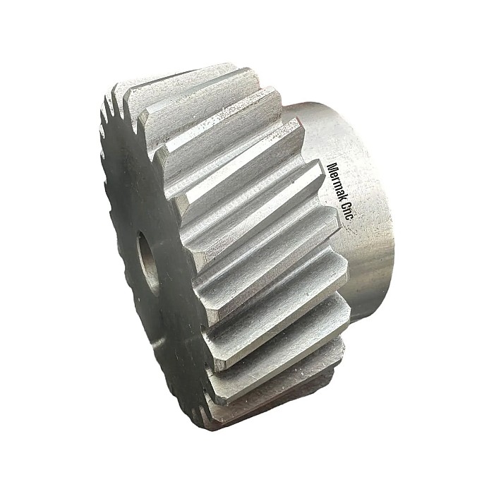
- Mechanical Mounting and Alignment: The backlash between the pinion and the rack is critical for accuracy and gear life. Excessive tight mounting increases friction, while excessive looseness causes backlash and vibration. Adjustments should generally be made with the minimum backlash value recommended by the manufacturer. Additionally, ensure that the pinion is mounted perfectly parallel and perpendicular to the rack. Misalignment leads to premature wear and efficiency loss in the gears.
- Lubrication: Regular and proper lubrication of the rack and pinion gears reduces friction, prevents wear, and extends the system’s lifespan. Industrial greases or oils suitable for ambient conditions and operating time under load should be used. Lack of lubrication or incorrect lubricant selection can lead to gear jamming and motor overload.
- Thermal Management: Stepper motors tend to heat up, especially when operating at high currents and under continuous load. Keeping the motor’s operating temperature within the limits specified by the manufacturer is vital for performance and longevity. If necessary, consider installing a heat sink on the motor or using forced air cooling (fan). Excessive heating can lead to weakening of the motor’s magnets and loss of torque.
- Cable Management and Electromagnetic Interference (EMI): Stepper motor cables should be kept separate from power lines and other signal cables, and shielded cables should be used if possible. Proper grounding should be implemented, and cables should be routed neatly within cable trays. Incorrect wiring can lead to signal noise, erratic motor operation, or missed steps. In moving systems, it is also important for cables to be flexible and resistant to wear.
- Feedback (Encoder Usage): Stepper motors typically operate with open-loop control. However, in critical applications or situations with high load fluctuations, closed-loop control can be achieved with an encoder attached to the motor shaft. This helps detect and compensate for missed steps, thereby increasing positioning accuracy and reliability. Stepper motors with encoders can offer performance close to servo motors while maintaining a cost advantage.
- Resonance Problems: Stepper motors tend to resonate at certain speeds. This can cause the motor to vibrate, generate noise, and lose torque. Methods to avoid resonance zones include using microstepping, enabling the driver’s anti-resonance features, or adding mechanical damping elements. Proper matching of system inertia also reduces the risk of resonance.
Common Problems and Solutions
Common problems encountered in stepper motor rack and pinion systems and their solutions are detailed below:
-
Missed Steps: The motor fails to complete the commanded steps.
- Causes: Overloading (load exceeding motor’s torque capacity), insufficient acceleration/deceleration times, resonance, incorrectly set driver current, mechanical jamming or backlash.
- Solutions: Resizing the motor to select a higher torque model, extending acceleration/deceleration ramps, checking motor driver current settings, using microstepping, inspecting the mechanical system to eliminate friction or jamming, adding an encoder for feedback.
-
Overheating: The motor’s temperature rises above its normal operating range.
- Causes: High driver current, insufficient cooling, continuous operation under high load, high ambient temperature, incorrect motor sizing.
- Solutions: Adjusting driver current according to motor’s rated values, providing additional cooling with a heat sink or fan, optimizing the motor’s duty cycle, using a larger motor, or lowering ambient temperature.
-
Vibration and Noise: The motor or system vibrates and makes abnormal noise.
- Causes: Resonance, incorrect microstepping settings, mechanical backlash, unbalanced load, incorrect mounting.
- Solutions: Using the driver’s anti-resonance features, increasing the microstepping ratio, checking and tightening mechanical connections or eliminating backlash, adding vibration damping elements to the system, matching motor and load inertia.
-
Inaccurate Positioning: Failure to reach the target position or position drift over time.
- Causes: Missed steps, rack-pinion backlash, mechanical slippage, encoder malfunction (if used), noise in the control signal.
- Solutions: Addressing missed step issues, adjusting mechanical backlash or using zero-backlash gear systems, checking encoder connections and functionality, protecting cabling from EMI, performing periodic system calibration.
-
Lower Than Expected Speed or Torque: Motor performing below expected specifications.
- Causes: Insufficient supply voltage or current, incorrect motor/driver matching, mechanical friction or jamming, motor losing torque at high speeds.
- Solutions: Ensuring the power supply provides correct voltage and current, ensuring the driver is compatible with the motor and correctly set, thoroughly inspecting the mechanical system to eliminate sources of friction, checking the motor’s torque-speed curve to evaluate the suitability of the operating point.
Expert Advice
Selecting a stepper motor for rack and pinion systems is a critical step for the success of industrial automation applications. This process requires a holistic approach, evaluating system dynamics, mechanical tolerances, environmental factors, and cost-effectiveness, rather than just focusing on motor torque values. Fundamental engineering calculations such as load inertia, friction, speed, and precision requirements form the basis of correct motor sizing. However, field experience is indispensable in translating this theoretical knowledge into practical applications. The meticulousness of mechanical assembly, correct lubrication regimes, effective thermal management, and electromagnetic compatibility are operational details that directly affect the system’s longevity and trouble-free operation. Problems such as missed steps, overheating, or vibration are usually caused by incorrect motor sizing, faulty driver settings, or deficiencies in the mechanical system. In such cases, performing a comprehensive fault analysis and implementing the solutions mentioned above will ensure that the system quickly returns to normal operation. It should be remembered that every application has its unique requirements, and therefore, detailed examination of manufacturer technical data sheets and, if necessary, obtaining supplier engineering support, are of great importance in making the most accurate and reliable selection. A correctly selected and optimized stepper motor rack and pinion system will provide high efficiency, precision, and reliability in your automation projects, creating a competitive advantage.
FAQ
Why are stepper motors commonly used in rack and pinion systems?
Stepper motors are often preferred in rack and pinion systems due to their cost-effectiveness, simple control mechanism, and high potential for precise positioning. They convert electrical pulses into mechanical rotational steps, allowing for accurate linear motion along the rack.
What are the critical technical parameters for selecting a stepper motor for a rack and pinion system?
Key factors include torque requirements (holding and dynamic), speed requirements, positioning accuracy (step angle, microstepping, rack module), inertia matching between the motor and load, power supply and driver compatibility, and environmental conditions.
What are the common problems encountered with stepper motors in rack and pinion systems and how can they be resolved?
Common issues include missed steps (due to overload, incorrect acceleration, or resonance), overheating (from high current or insufficient cooling), vibration and noise (from resonance or mechanical backlash), and inaccurate positioning. Solutions involve proper motor sizing, driver adjustments, mechanical alignment, lubrication, and thermal management.
How important is inertia matching in stepper motor selection for rack and pinion systems?
Inertia matching is crucial to ensure the motor's rotor inertia is proportional to the load's inertia. A ratio between 1:1 and 1:10 is typically recommended. Poor inertia matching can lead to control difficulties, vibration, and missed steps, affecting the system's dynamic response and stability.
Can an encoder improve the performance of a stepper motor in a rack and pinion system?
While stepper motors typically use open-loop control, adding an encoder provides closed-loop feedback. This helps detect and compensate for missed steps, significantly improving positioning accuracy and reliability, especially in critical applications or those with fluctuating loads.