



































































































































How to Minimize Torque Loss in Stepper Motors for Industrial Applications
📑 Table of contents (Click to open)
Introduction and Technical Analysis
Stepper motors, at the heart of industrial automation systems, play an indispensable role in numerous applications requiring precise positioning and speed control. They are widely used in systems such as robotic arms, CNC machines, 3D printers, labeling machines, and conveyor belts. One of the most significant advantages of stepper motors is their ability to provide high-accuracy position control, often without feedback (open-loop). However, the sustainability of this advantage depends on the motor’s ability to efficiently transmit its torque under load. Torque loss is a critical factor that directly impacts stepper motor performance and can severely reduce the overall efficiency, accuracy, and reliability of the system. Torque loss occurs when the motor fails to produce the expected torque at a specific speed or under load; this can lead to step losses, positioning errors, vibration, overheating, and even system failures. This technical article and field guide aim to provide industrial automation professionals with a comprehensive roadmap to understand, diagnose, and minimize torque loss in stepper motors. We will address the topic from various angles, including motor selection, driver technologies, mechanical integration, and software optimization, offering practical solutions to challenges encountered in the field.
Operating Principle and Technical Data
Stepper motors are brushless DC motors that convert electrical energy into mechanical motion. They operate on the principle that their rotors move at specific angles (steps) through interaction with magnetic fields on the stator. Sequential pulses applied to the windings of a stepper motor cause the rotor to rotate by a specific step angle with each pulse. This step angle depends on the motor’s physical design (number of poles, gear structure) and is typically standard values such as 0.9°, 1.8°, or 3.6°. The torque produced by the motor is directly related to the amount of current flowing through the windings and the strength of the magnetic field. Higher current means a stronger magnetic field and thus higher torque. However, as the motor speed increases, the back EMF (electromotive force) generated in the windings and the inductance of the windings make it difficult for the current to reach the desired level. This situation is the main physical limitation that causes a significant drop in torque, especially at high speeds.
Key technical data affecting stepper motor performance include:
- Holding Torque: The maximum torque the motor can generate to maintain the rotor’s position when stationary and nominal current is applied. This indicates the motor’s static load capacity.
- Pull-in Torque: The maximum torque at which the motor can start from zero speed under load and accelerate to a certain speed without losing any steps.
- Pull-out Torque: The maximum torque the motor can sustain at a specific speed without losing steps. This is typically the value shown in the torque-speed curve.
- Step Angle: The angle the motor rotates with each pulse. A smaller step angle means higher resolution and smoother motion.
- Phase Current: The nominal current flowing through the motor windings. Directly affects torque.
- Phase Inductance: The inductive resistance of the windings. High inductance makes it difficult for current to rise at high speeds and accelerates torque drop.
- Rotor Inertia: The resistance of the rotor to rotational motion. High inertia requires slower acceleration and deceleration, which increases torque requirements.
- Driver Voltage: The maximum voltage the driver can apply to the motor. Higher voltage allows current to rise faster at high speeds, delaying torque drop.
In industrial applications, the selection of the motor and its driver must consider the dynamic requirements of the application (speed, acceleration, load inertia, external forces). Incorrect selections lead to torque loss and the system’s inability to perform as desired.
| Parameter | Value/Description |
|---|---|
| Holding Torque | 0.5 Nm – 20 Nm (Varies by motor size) |
| Step Angle | 1.8° (Standard 200 steps/revolution) or 0.9° (400 steps/revolution) |
| Phase Current | 0.5 A – 6 A (Depends on motor power) |
| Phase Inductance | 1 mH – 15 mH (Lower values preferred for high-speed performance) |
| Rotor Inertia | 10 g·cm² – 500 g·cm² (Varies by motor size) |
| Maximum Speed | 500 RPM – 3000 RPM (Varies depending on load and driver) |
| Operating Temperature Range | -10°C to +50°C (Must be checked according to manufacturer datasheet value.) |
| Driver Type | Constant Current (Chopper) or Hybrid Servo Driver (Varies by performance) |
Field Considerations for Stepper Motor Optimization
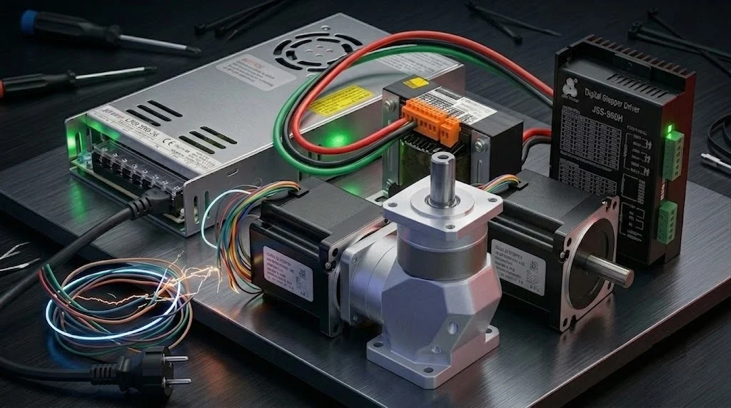
- Correct Motor and Driver Selection: The maximum torque, speed, and inertia load required by the application must be carefully calculated. The holding torque of the selected motor should be at least 20-30% higher than the maximum torque required by the application. The driver must be able to supply the motor’s nominal current and preferably have a high supply voltage that can overcome the motor’s inductance (e.g., a 48V or 72V driver for a 24V motor). High-voltage drivers ensure rapid current injection into the windings even at high speeds, minimizing torque loss. Drivers with high micro-stepping capability (e.g., 256 microsteps) provide smoother motion and resonance reduction.
- Micro-stepping and Resonance Management: Micro-stepping increases the smoothness of motion by dividing the motor’s step angle into smaller increments, reducing vibration and noise, especially at low speeds. However, very high micro-stepping ratios can lead to a reduction in torque for each micro-step, which can cause issues in precise positioning. It is crucial to select an optimized micro-stepping ratio (e.g., 8x or 16x). Stepper motors tend to resonate at certain speeds. These resonance frequencies can significantly reduce motor torque, leading to step loss. Anti-resonance features in drivers should be utilized, or the operating speed profile should be adjusted to avoid resonance zones. External vibration dampers can also be an effective solution.
- Current Setting and Thermal Management: Stepper motor drivers precisely control the current supplied to the motor windings. Correctly setting the motor’s nominal current is critical. Insufficient current leads to torque loss and missed steps, while excessive current causes the motor to overheat and shortens its lifespan. The motor’s continuous operating temperature must be kept within the limits specified by the manufacturer. If necessary, passive or active cooling solutions (fans, heat sinks) should be used. High ambient temperatures can also negatively affect motor performance; in such cases, the motor’s thermal derating curves must be considered.
- Cabling and Noise Reduction: The cross-section of the cables between the motor and the driver must be appropriate for the current carrying capacity and thick enough to minimize voltage drop over long distances. Additionally, motor cables should be kept separate from other signal cables, and shielded cables should be used to reduce electrical noise (EMI/RFI). Incorrect or poor-quality cabling can disrupt signal integrity, leading to torque loss or erratic operation. Grounding arrangements are also very important for the electrical stability of the system.
- Mechanical Mounting and Alignment: The surface on which the motor is mounted must be robust and vibration-free. Proper alignment of mechanical coupling elements such as couplings or belt-pulley systems is vital. Misalignment causes radial or axial loading on the shaft, increasing friction, leading to torque loss, and shortening the life of motor bearings. When selecting couplings, flexible couplings that can compensate for small alignment errors in the system may be preferred. Loose connections or worn mechanical components can also cause torque loss. Regular mechanical inspection and maintenance should be performed.
- Load Inertia and Speed Profile Optimization: The inertia of the load to be driven by the motor should be close to or less than the motor’s rotor inertia. The ratio of load inertia to rotor inertia should generally not exceed 10:1. High-inertia loads cause the motor to expend more torque during acceleration and deceleration. The application’s speed profile (acceleration, constant speed, deceleration) should be optimized considering the motor’s torque-speed curve. Abrupt accelerations or decelerations should be avoided, and ramps should be smoothed to not exceed the motor’s maximum torque capacity. This prevents torque loss and missed steps, especially at high speeds.
- Feedback Systems (Closed-Loop): While open-loop stepper motors are generally sufficient, in critical applications, feedback systems such as encoders can be integrated to completely eliminate torque loss and increase system reliability. These systems continuously monitor the motor’s actual position and allow the driver to make corrections in case of step loss. Such hybrid stepper-servo systems combine the simplicity and cost advantage of a stepper motor with the precision and reliability of a servo motor.
Common Problems and Solutions in Stepper Motor Applications
Problem 1: Missed Steps and Positioning Errors
Causes: This is the most common symptom of torque loss. It can be due to the motor being unable to handle the load, excessively fast acceleration/deceleration, incorrect current setting, motor operating at its resonance frequency, mechanical jamming or excessive friction, or weak/noisy pulse signals from the driver.
Solutions: First, ensure that the motor and driver meet the application’s torque and speed requirements. If necessary, choose a more powerful motor or a higher-voltage driver. Set the driver current correctly according to the motor’s nominal value. Extend acceleration and deceleration ramps to match the motor’s torque-speed curve. Optimize the driver’s micro-stepping settings (8x or 16x is often a good starting point) and enable the resonance damping feature. Check for friction in the mechanical system, lubricate or replace bearings and moving parts. Check cabling, use shielded cables, and ensure signal integrity. If necessary, consider upgrading to a hybrid servo system by adding an encoder.
Problem 2: Overheating
Causes: Excessive current flowing through motor windings, insufficient cooling, continuous operation under high load, high ambient temperature, or operating the motor at a voltage lower than its nominal rating (causing it to draw more current to compensate).
Solutions: Reduce the current setting on the driver to the motor’s nominal current value. Review the motor’s duty cycle and load profile; try to reduce situations where the motor continuously operates at maximum torque. Add a cooling fan to or near the motor. Use specific heat sinks for larger motors. Relocate the motor to a cooler environment or take measures to reduce the ambient temperature. If the driver voltage is too low, the motor may tend to draw more current; using a higher-voltage driver can help produce the same torque with lower current.
Problem 3: Vibration and Noise
Causes: Resonance, low micro-stepping settings, mechanical looseness or alignment issues, motor operating at its natural frequencies, or poor quality of the pulse waveform from the driver.
Solutions: Increase the micro-stepping ratio to smooth out motor movement. Enable the driver’s resonance damping or vibration reduction features. Check mechanical mounting, tighten loose screws or connections. Ensure couplings are correctly aligned and flexible. Add vibration-absorbing mounting feet or special dampers to the system. Adjust the motor’s operating speed to keep it away from resonance frequencies. Checking the driver’s pulse output quality with an oscilloscope can be beneficial.
Problem 4: Irregular Movement or Stalling at Low Speeds
Causes: Low-resolution micro-stepping, mechanical friction or stick-slip effect, the influence of the motor’s detent torque (especially at very low speeds).
Solutions: Increase the micro-stepping ratio to allow the motor to move in smaller steps and more smoothly. Reduce friction in the mechanical system and ensure smooth operation. Especially in linear motion systems, ensure that linear guide rails, ball screws, and bearings are clean and lubricated. To reduce the effect of detent torque, try using
FAQ
What is torque loss in stepper motors and why does it happen?
Torque loss in stepper motors occurs when the motor cannot produce the expected torque at a specific speed or under load, leading to missed steps, positioning errors, vibration, and overheating. This is often due to factors like insufficient current, high speed, resonance, or mechanical issues.
What are the key strategies to minimize torque loss in industrial stepper motor applications?
To minimize torque loss, ensure correct motor and driver selection, optimize micro-stepping settings, manage resonance, set current accurately, implement effective thermal management, use proper cabling, ensure precise mechanical mounting and alignment, and optimize load inertia and speed profiles. For critical applications, consider hybrid stepper-servo systems with encoders.
What are the common problems associated with torque loss and how can they be resolved?
Common issues include missed steps, overheating, vibration, noise, and irregular movement at low speeds. Solutions involve optimizing driver settings (current, micro-stepping, anti-resonance), improving mechanical integrity (alignment, lubrication), ensuring proper cooling, and using shielded cables. For persistent issues, a hybrid servo system might be necessary.
What technical parameters are most important for stepper motor performance in industrial settings?
The main technical parameters are holding torque, pull-in torque, pull-out torque, step angle, phase current, phase inductance, rotor inertia, and driver voltage. Understanding these helps in selecting the right motor and driver for specific application requirements.
How do high-voltage drivers contribute to reducing torque loss at high speeds?
High-voltage drivers help minimize torque loss at high speeds by allowing current to rise faster in the motor windings, overcoming the effects of back EMF and inductance. This ensures that the motor receives sufficient current to maintain torque even during rapid movements.
