



































































































































Understanding Step Motor Cables: Selecting the Right Cable Cross-Section and Length
📑 Table of contents (Click to open)
A step motor cable is the critical link between your motor and its driver, ensuring power and signal transmission. Proper selection of cable cross-section and length is vital to minimize voltage drop, maintain signal integrity, and prevent electromagnetic interference. This ensures your industrial CNC router machine and automation systems operate efficiently and reliably.
Practical notes for CNC router, automation and industrial motion systems.
What is a Step Motor Cable?
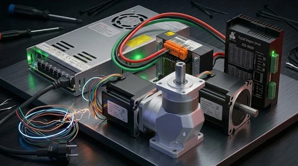
In industrial automation, step motors are essential for precise positioning and motion control, enabling accurate movements through discrete angular steps. The performance of these motors is significantly influenced by the step motor cable connecting them to their driver (controller). This cable’s primary function is to transmit power signals from the driver to the motor’s coils, energizing them sequentially to produce rotation. In some configurations, it may also carry feedback signals from encoders or control signals for brakes. The correct cable selection directly impacts the motor’s torque, speed capabilities, and overall system stability. An improperly chosen cable can lead to voltage drops, reduced torque, signal degradation, and even system failures. Therefore, accurately determining the cable’s cross-section and length is crucial for the success of industrial automation applications.
Operating Principles and Technical Considerations
Selecting the appropriate step motor cable involves evaluating numerous factors, including the motor’s electrical specifications, the driver’s output capabilities, and the environmental conditions of operation. A well-chosen cable guarantees a long-lasting, efficient, and trouble-free system.
Cable Cross-Section: Current Carrying Capacity and Voltage Drop
The cable cross-section must be adequate to safely handle the motor’s nominal current and keep voltage drop within acceptable limits. Voltage drop occurs due to the cable’s resistance, reducing the voltage delivered to the motor coils. Excessive voltage drop diminishes motor torque and speed performance, potentially causing missed steps.
- Motor Current (Amperes): Identify the nominal current per phase (RMS or peak) for your step motor. Each conductor in the cable must safely carry this current. The current setting on the motor driver is a key reference.
- Cable Length: Longer cables have higher resistance, leading to increased voltage drop. Thicker cross-sections are necessary for longer runs.
- Ambient Temperature and Cable Bundling: High ambient temperatures or bundling multiple cables together can impede heat dissipation, reducing the cable’s current carrying capacity. Consider a slightly thicker gauge in such scenarios.
- Allowable Voltage Drop: Aim for a total voltage drop not exceeding 2% to 5% of the supply voltage. This threshold may vary based on system sensitivity and motor criticality. The voltage drop (ΔV) can be estimated using: ΔV = 2 * I * R_per_unit_length * L, where I is current, R is resistance per unit length, and L is cable length (factor of 2 accounts for the round trip).
- Standards: Cable cross-sections are specified in mm² or AWG (American Wire Gauge). Lower AWG numbers indicate thicker conductors.
Cable Length: Signal Integrity and Interference Effects
Beyond voltage drop, cable length significantly impacts signal integrity and susceptibility to electromagnetic interference (EMI/RFI).
- Capacitance and Inductance: Extended cable lengths increase capacitance and inductance. This can distort Pulse Width Modulation (PWM) signals from step motor drivers, causing signal delays and incorrect motor steps, especially at high frequencies.
- EMI/RFI Susceptibility: Long cables are more prone to picking up electromagnetic noise from adjacent equipment (contactors, inverters, power supplies). This noise can corrupt control signals, leading to erratic operation. Using shielded cables is highly recommended for longer runs to block external interference.
- Manufacturer Recommendations: Step motor driver manufacturers often provide guidelines for maximum cable lengths suitable for specific motor-driver combinations. Adhering to these recommendations is key to ensuring optimal performance.
- Cable Type and Construction:
- Conductor Material: High-conductivity copper is standard.
- Insulation Material: PVC, PUR, or PE offer varying degrees of flexibility, temperature resistance, and chemical resistance. For dynamic applications like robotics or cable carriers, flexible PUR or TPE insulation is preferred.
- Shielding: Braided or foil shielding minimizes electromagnetic noise. Braided shielding offers better mechanical protection and low-frequency performance, while foil is effective at high frequencies. Combined shielding options exist.
- Outer Jacket: Provides mechanical protection against abrasion, oil, UV radiation, and chemicals. Select based on the operating environment.
- Flex Life: For continuous motion applications, the cable’s flex life (number of bending cycles) is critical. Cables designed for high flex life feature specialized conductor stranding and insulation.
| Parameter | Value/Description |
|---|---|
| Motor Phase Current (RMS) | 1.0 A – 6.0 A (Typical) |
| Recommended Cable Cross-Section | 0.5 mm² (20 AWG) – 2.5 mm² (14 AWG) (Depends on current and length) |
| Maximum Cable Length (Shielded) | 10 meters – 50 meters (Varies by driver and motor model) |
| Allowable Voltage Drop | 2% – 5% of Supply Voltage |
| Shielding Type | Braided Copper Shield, Aluminum Foil, or Combined (for EMI/RFI protection) |
| Insulation Material | PVC (Static), PUR/TPE (Flexible, Oil Resistant), PE (Low Capacitance) |
| Operating Temperature Range | -20°C to +80°C (Depending on cable type) |

Field Considerations
- Environmental Conditions and Mechanical Protection: Assess the operating environment’s temperature, humidity, chemical exposure (oils, acids), UV radiation, and mechanical abrasion risks. For instance, use oil-resistant PUR jacketed cables in machine tool environments and UV-resistant, waterproof cables outdoors. For applications with continuous movement or vibration, select cables with high flex life and appropriate mechanical robustness.
- Cable Routing and Management: Proper cable routing is essential to prevent damage and interference. Avoid running power cables parallel to high-current signal cables. Use cable trays, conduits, or flexible conduits for protection and organization. Ensure sufficient bend radius is maintained, especially for flexible cables, to avoid premature failure.
- Grounding and Shielding Termination: Correctly grounding the cable shield is critical for effective EMI/RFI suppression. Typically, the shield should be grounded at the driver end. Consult the driver manufacturer’s documentation for specific grounding instructions. Improper grounding can sometimes worsen interference.
- Connector Quality: Use high-quality connectors that provide secure electrical contact and mechanical integrity. Ensure connectors are rated for the current and voltage, and are suitable for the environment (e.g., IP-rated for dust and water resistance).
Conclusion
Selecting the correct step motor cable is not merely a matter of connecting two points; it’s a critical engineering decision that directly impacts the performance, reliability, and lifespan of your automated machinery, including CNC router machines. By carefully considering the motor’s current requirements, the total cable length, potential voltage drops, signal integrity needs, and environmental factors, you can choose a cable that ensures optimal operation. Investing in the right cable, particularly a shielded one for longer runs or noisy environments, prevents costly downtime and performance issues. For expert advice on selecting the best components for your industrial CNC router or other automation systems, consult with our specialists.
Ready to optimize your motion control system? Request a quote on WhatsApp for tailored solutions and expert guidance.
Related product categories: Uncategorized · 0.75 Kw Variable Frequency Drives · 06B-2 Roller Chain Sprocket
