No products in the cart.
Mermak CNC Technical Support: Top 50 FAQs and Solutions for Industrial Buyers
Contents
Mermak CNC Technical Support: Field Guide and Technical Article
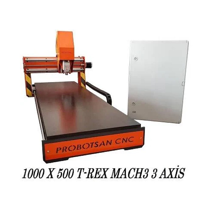
Introduction and Technical Analysis
At the heart of industrial automation, CNC (Computer Numerical Control) machines are indispensable for modern manufacturing processes. They enable the production of complex parts by offering precision, speed, and repeatability. Mermak CNC systems have established a significant position in the industry with their innovative solutions and high-performance machines. However, for these complex systems to operate efficiently and continuously, comprehensive technical knowledge and an effective support mechanism are essential. This field guide and technical article aim to provide in-depth answers to the most frequently asked questions by Mermak CNC users and technical support teams, helping them fully utilize the potential of their machines. The goal is not only to find immediate solutions to problems but also to develop a proactive approach by understanding the fundamental operating principles, maintenance requirements, and performance optimization methods of the machines. This guide will serve as a critical resource for understanding the integration of mechanical, electrical, electronic, and software components, and for diagnosing and resolving potential malfunctions. With insights distilled from the experience of industry experts, the objective is to extend the lifespan of Mermak CNC machines, minimize downtime, and increase production efficiency.
Operating Principle and Technical Data
Mermak CNC machines operate on the principle of shaping material through cutting tools that move along multiple axes, controlled by a computer numerical control unit. Essentially, the geometry of a part designed in CAD/CAM software is transferred to the machine using standard programming languages such as G-code and M-code. These codes are interpreted by the control unit and sent as motion commands to servo motors. Servo motors, via ball screws and linear guide rails, ensure that the tool or worktable moves precisely to the desired position and speed. Thanks to feedback systems (encoders or resolvers), the control unit continuously monitors the actual position of the axes and instantly corrects any deviations by comparing them with the target position. This closed-loop control system provides high positioning accuracy and repeatability. The spindle motor is a critical component where the cutting tool is mounted and rotates at high speeds to process the material. Spindle speed and feed rate are programmed according to the type of material being processed, the tool geometry, and the desired surface quality. Modern Mermak CNC machines are equipped with automatic tool changers, cooling systems, chip conveyors, and various sensors. These sensors continuously monitor machine status (temperature, pressure, position), contributing to safety and performance optimization. The machine construction is typically made of cast iron or special alloys to absorb vibration and provide high rigidity. Components such as power supplies, servo drives, PLC (Programmable Logic Controller), and contactors located in the electrical cabinet manage all electrical and electronic functions of the machine. The operator panel provides an interface for users to load programs, set parameters, and manually control the machine. Mermak CNC machines can generally be used for many different machining operations such as milling, turning, drilling, and grinding, and can process a wide range of materials including metal, plastic, and composites.
| Parameter | Value/Description |
|---|---|
| Working Area (X/Y/Z) | Varies by model; typically between 500x400x350 mm and 2000x1000x800 mm |
| Spindle Power | 7.5 kW – 30 kW (Continuous), can be higher in high-performance models. |
| Max Spindle Speed | 8,000 rpm – 24,000 rpm (Can go up to 40,000 rpm for high-speed machining) |
| Axis Rapid Traverse (X/Y/Z) | 24 m/min – 60 m/min (Varies depending on model and control unit) |
| Positioning Accuracy | ±0.005 mm (According to ISO 230-2 standard, varies by model) |
| Repeatability | ±0.003 mm (According to ISO 230-2 standard, varies by model) |
| Tool Type/Capacity | BT40/CAT40/HSK63; 20-30 tool capacity standard, optional 40+ tools |
| Control Unit Type | Fanuc, Siemens, Heidenhain (Can be integrated with Mermak’s proprietary interfaces) |
| Supply Voltage | 3 Phase AC 380V ±%10, 50/60Hz (Must be checked according to country standards and machine model) |
Field Considerations
- Strict Adherence to Periodic Maintenance Program: Periodic maintenance is critical for the long-term and trouble-free operation of Mermak CNC machines. This is not limited to lubrication and filter changes; it includes steps such as electrical cabinet cleaning, checking cable connections, monitoring coolant level and concentration, checking hydraulic/pneumatic system pressures, and testing the functionality of the tool magazine mechanism. Regular cleaning and lubrication of axis linear guides and ball screws, in particular, prevent wear and maintain positioning accuracy. Keeping regular maintenance records allows for early diagnosis of potential problems and the implementation of preventive measures.
- Tool Management and Cutting Insert Condition: Tool selection and condition have a direct impact on machining quality and machine performance. The correct tool material, geometry, and coating must be suitable for the material being processed and the operation. The wear status of cutting inserts should be regularly checked and replaced when necessary. Worn or incorrectly selected tools reduce surface quality, shorten tool life, cause unnecessary load on the spindle motor and axes, and can damage machine components. Ensuring that tool offsets and compensations are entered correctly is essential for dimensional accuracy.
- Environmental Conditions and Occupational Safety: The temperature, humidity, vibration, and dust levels of the environment where CNC machines are located directly affect machine performance and lifespan. Stable temperature and low humidity levels are particularly important for the control unit and sensitive electronic components. Contamination from chips and coolant splashes can impair the functionality of sensors and moving parts. Therefore, regular cleaning and appropriate ventilation systems are necessary. Furthermore, it is vital that operators have completed occupational safety training, use protective equipment, and strictly adhere to safety procedures in the machine operating area (e.g., safety doors closed, emergency stop buttons functional).
- Programming Practices and Collision Prevention: Effective and safe CNC operation relies heavily on programming practices. G-code optimization reduces unnecessary movements, shortening cycle time and increasing tool path efficiency. However, errors made during programming can lead to tool/workpiece collisions. Such collisions can cause serious damage to the spindle motor, tool magazine, workpiece, and even machine axes. Therefore, every new program must be carefully tested using simulation software or in dry run mode on the machine. Ensure that tool length and diameter compensations are entered correctly, zero point settings are precise, and safety distances are sufficient.
Common Problems and Solutions
Technical problems encountered in Mermak CNC machines are generally mechanical, electrical, or software-related. Here are the most common scenarios and solution approaches:
1. Axis Movement Problems (Vibration, Sticking, Positioning Error):
- Problem: Vibration, noise, or sticking felt during axis movement; dimensional errors or surface undulations after machining.
- Possible Causes: Incorrect servo motor settings (gain), wear/contamination in linear guides or ball screws, mechanical backlash, encoder feedback issues, servo drive malfunction.
- Solution:
- First, check the mechanical condition of the axes: Clean and lubricate the linear guides. Manually check for backlash in the ball screws.
- Check servo motor and drive parameters (especially gain settings). Compare with standard values in the machine manual and make adjustments if necessary.
- Test encoder cable connections and the encoder itself. Dirty or damaged encoders can provide incorrect feedback signals.
- If there is mechanical backlash, adjust the ball screw nut or replace worn components.
- Check the servo drive for error codes. Test or replace the drive if necessary.
2. Spindle Motor Problems (Excessive Noise, Overheating, Speed Fluctuation):
- Problem: Abnormal noises from the spindle motor, excessive overheating, failure to operate at programmed speed, or speed fluctuations.
- Possible Causes: Wear of spindle motor bearings, lack of lubrication, spindle motor or inverter malfunction, insufficient cooling system (if liquid-cooled).
- Solution:
- Check spindle motor bearings. Worn bearings cause noise and vibration. Replace bearings if necessary.
- Ensure the spindle lubrication system (automatic or manual) is working properly and the oil level is sufficient.
- Manually check the temperature of the spindle motor. If there is excessive overheating, check the motor windings or cooling fan.
- Check the inverter (VFD) for error codes. Ensure inverter parameters are set correctly and output voltage/frequency is stable.
- For liquid-cooled spindle motors, check the coolant level, pump, and filters.
3. Tool Changer Errors (Tool Drop, Jamming, Incorrect Tool Selection):
- Problem: Tool dropping, jamming in the magazine, or the control unit selecting the wrong tool during tool change.
- Possible Causes: Insufficient pneumatic/hydraulic pressure, contamination/malfunction of tool changer sensors, mechanical adjustment faults, wear of tool holders, error in PLC program.
- Solution:
- Check air or hydraulic pressure. Ensure the tool holder mechanism operates with sufficient force.
- Check position sensors (proximity switches) on the tool changer arm and magazine. Dirty or faulty sensors can provide incorrect signals.
- Check mechanical adjustments (arm travel distance, clamping force) and adjust if necessary.
- Inspect tool holders for wear/damage on conical surfaces or internal parts.
- Review parameters and logic related to the tool change cycle in the PLC program.
4. Control Unit Errors and Alarm Codes:
- Problem: Alarm codes appearing on the control unit, machine stopping operation, operating system freezing.
- Possible Causes: Electrical noise (EMC), power supply problems, memory card malfunction, parameter errors, software issues, sensor errors.
- Solution:
- Read the alarm code from the machine manual or control unit guide and understand its meaning. Most alarm codes provide valuable clues about the root cause of the problem.
- Check the power supplies of the control unit and drives. Voltage drops or fluctuations can cause problems.
- Ensure machine parameters are correct. An incorrectly entered parameter can cause the machine to alarm.
- Check all cable connections, especially signal cables. Loose or damaged cables can lead to electrical noise and communication errors.
- Ensure the control unit’s cooling fans are working and airflow is not obstructed.
- If the problem appears to be software-related, restart the control unit or consider restoring from the last backup point.
5. Surface Quality and Dimensional Accuracy Problems:
- Problem: Roughness, cracking, burrs on the surface of machined parts, or falling outside desired dimensional tolerances.
- Possible Causes: Tool wear, incorrect cutting parameters (speed, feed, depth of cut), insufficient workpiece clamping rigidity, lack of machine rigidity, vibration, insufficient coolant.
- Solution:
- Check the condition of the tool. Dull or incorrectly sharpened tools cause poor surface quality.
- Adjust cutting parameters (spindle speed, feed rate, depth of cut) to suit the material being processed and the tool. Follow manufacturer recommendations.
- Ensure the workpiece is securely clamped to the machine table or fixture. Loose clamping leads to vibration and dimensional errors.
- Check the overall rigidity of the machine. Backlash in axes or loose connections increase vibration.
- Ensure coolant is used at sufficient flow rate and correct concentration. Insufficient cooling shortens tool life and degrades surface quality.
- Check machine calibration (axis offsets, tool zeroing) and recalibrate if necessary.
Expert Advice
Mermak CNC machines form the backbone of modern manufacturing facilities, and the optimal performance of these complex systems requires detailed technical knowledge and a proactive maintenance approach. This field guide provides a roadmap for experts and technicians in the industrial automation sector to find quick and effective solutions to technical problems they encounter. It should be remembered that one of the most important factors directly affecting the lifespan and efficiency of a CNC machine is regular and conscious maintenance. Periodic checks, proper tool management, ensuring appropriate environmental conditions, and continuous operator training will prevent potential malfunctions and minimize unplanned downtime. Every problem encountered offers an opportunity to better understand the machine’s operating principles and to resolve similar situations faster in the future. Especially, correctly interpreting alarm codes, meticulously checking mechanical and electrical connections, understanding system parameters, and effectively using documentation provided by the manufacturer are critical steps in the troubleshooting process. Mermak’s technical support teams are a valuable resource even for the most complex problems, guaranteeing the continuous operation of your machines with in-depth expertise and original spare parts support. The information in this guide, combined with field experience, will contribute to operating your Mermak CNC machines at maximum performance, safely and efficiently, and will increase your competitiveness in production processes. Continuous learning and adaptation are key to success in this dynamic sector. Request a quote on WhatsApp today to learn more about Mermak CNC solutions and support.
FAQ
How do Mermak CNC machines fundamentally operate?
Mermak CNC machines are controlled by a computer unit that directs cutting tools along multiple axes. They use G-code and M-code to translate CAD/CAM designs into precise movements, driven by servo motors, ball screws, and linear guide rails. Feedback systems like encoders ensure high positioning accuracy and repeatability.
What are the most common technical problems encountered with Mermak CNC machines?
Common issues include axis movement problems (vibration, positioning errors), spindle motor issues (noise, overheating, speed fluctuations), tool changer malfunctions (tool drops, jamming), control unit errors (alarm codes, freezing), and problems with surface quality or dimensional accuracy.
What are the key maintenance practices for Mermak CNC machines?
Regular periodic maintenance, including cleaning and lubricating linear guides and ball screws, checking electrical connections, monitoring coolant levels, and testing tool magazine functionality, is crucial. Proper tool management, maintaining suitable environmental conditions, and continuous operator training also prevent issues.
How can I troubleshoot axis movement or spindle motor problems?
For axis movement issues, check servo motor settings, clean/lubricate linear guides, inspect ball screws for backlash, and test encoders. For spindle problems, examine bearings, lubrication, motor temperature, and inverter parameters. Always consult the machine manual for specific alarm codes.
What should I do if the tool changer malfunctions?
Ensure sufficient pneumatic/hydraulic pressure, check tool changer sensors for contamination or malfunction, verify mechanical adjustments, and inspect tool holders for wear. Review the PLC program for any errors related to the tool change cycle.