



































































































































Flexible Couplings vs. Rigid Couplings: A Comprehensive Guide for Industrial Applications
📑 Table of contents (Click to open)
- Flexible Coupling vs. Rigid Coupling: Where and When to Use Each in Industrial Automation – Introduction an...
- Flexible Coupling vs. Rigid Coupling: Operating Principles and Technical Data
- Flexible Couplings: Misalignment Tolerance and Vibration Damping
- Operating Principle:
- Types of Flexible Couplings:
- Application Areas:
- Rigid Couplings: High Torque and Precise Alignment Requirement
- Operating Principle:
- Types of Rigid Couplings:
- Application Areas:
- Flexible Coupling vs. Rigid Coupling: On-Site Considerations for Optimal Selection
- Flexible Coupling vs. Rigid Coupling: Common Problems and Solutions in the Field
- Common Problems and Solutions for Flexible Couplings:
- Common Problems and Solutions for Rigid Couplings:
- Flexible Coupling vs. Rigid Coupling: Conclusion and Expert Advice
- FAQ
Flexible Coupling vs. Rigid Coupling: Where and When to Use Each in Industrial Automation – Introduction and Technical Analysis
Power transmission mechanisms, at the heart of industrial automation systems, play a critical role in ensuring production continuity and efficiency. As fundamental components of these systems, couplings are mechanical elements that connect two separate shafts, transmitting torque from one shaft to another. However, this simple definition does not fully capture the engineering depth behind coupling selection and its impact on system performance. Correct coupling selection extends machine life, reduces maintenance costs, and prevents unexpected failures, while an incorrect choice can lead to severe damage, production losses, and safety risks. In this comprehensive field guide, we will delve into the differences, operating principles, advantages, disadvantages, application areas, and correct selection criteria for two main coupling types frequently encountered in the industrial automation sector: flexible couplings and rigid couplings. Our goal is to provide a practical and technical perspective that will help engineers and field technicians select the most suitable coupling type for their system needs. Both coupling types have their unique strengths and limitations, and this choice requires considering much more than just torque transmission, including factors such as shaft alignment tolerances, vibration damping, shock load absorption, and and environmental conditions.
Flexible Coupling vs. Rigid Coupling: Operating Principles and Technical Data
While the primary function of couplings is to transmit torque, how they achieve this transmission and their impact on the system creates a sharp distinction between flexible and rigid couplings. In this section, we will detail the operating principles, technical specifications, and typical use scenarios for both coupling types.
Flexible Couplings: Misalignment Tolerance and Vibration Damping
Flexible couplings, as their name suggests, are designed to compensate for a certain degree of parallel misalignment, angular misalignment, and axial misalignment between two shafts. This capability is provided by a flexible element within the coupling’s structure (elastomer, metal discs, springs, gears, chains, or bellows). The flexible element absorbs the stresses and forces caused by shaft misalignments, thereby extending the life of connected equipment (motors, pumps, reducers, bearings, etc.) and preventing excessive wear.
Operating Principle:
Flexible couplings transmit torque while simultaneously adapting to minor variations in moving shafts through their flexible elements. This flexibility also provides the ability to damp vibrations and absorb sudden shock loads within the system. These features are vital, especially in applications with dynamic loads and potential sources of vibration. Flexible couplings reduce the loads on the bearings of connected equipment, ensuring a longer lifespan for both the coupling and the equipment. Furthermore, some types of flexible couplings provide electrical insulation between the electric motor and the driven equipment, preventing the passage of electrical current in case of a fault.
Types of Flexible Couplings:
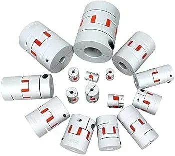
- Jaw Couplings: Typically consist of two metal hubs joined by an elastomeric spider or cushion. They offer moderate torque and misalignment capacity. Vibration damping properties are good.
- Disc Couplings: Utilize one or more thin metal disc packs. They have high torque and high misalignment capacity. They are maintenance-free and generally backlash-free.
- Gear Couplings: Composed of two hubs that mesh with internal and external gears. They have high torque and angular misalignment capacity but limited parallel misalignment capacity. They typically require lubrication.
- Grid Couplings: Use a spring-like grid element. They are effective in absorbing both torque and shock loads.
- Bellows Couplings: Used in precision applications, especially where high accuracy is required, such as with servo motors. They offer very low inertia and zero backlash.
- Elastomeric (Rubber, Sleeve, Pin-Bush) Couplings: Similar to jaw couplings, they use elastomeric elements but are designed with different geometries. They have a wide range of applications and provide good vibration damping.
Application Areas:
Flexible couplings are preferred in a wide range of applications such as pumps, compressors, conveyors, mixers, generators, fans, and general industrial drive systems. They are ideal particularly in environments where perfect shaft alignment is difficult to achieve or may change over time, and where vibrations and shock loads are expected. They are also critically important for precise and vibration-free motion in automation systems, motion control applications, and robotic systems.
Rigid Couplings: High Torque and Precise Alignment Requirement
Rigid couplings are types of couplings that connect two shafts precisely and firmly, causing them to behave as a single, long shaft. These couplings do not have the ability to compensate for any misalignment. On the contrary, they require perfect alignment of the connected shafts. Even the slightest alignment error can lead to excessive stress on the bearings and shafts of the connected equipment, causing failures in a short period.
Operating Principle:
Rigid couplings transmit torque by tightly clamping or bolting the shafts. Their inherent structure makes them extremely robust, capable of transmitting high torques without any loss of flexibility. They lack vibration damping or shock absorption capabilities; instead, they directly transmit all vibrations and shocks within the system. Therefore, in systems where rigid couplings are used, it must be ensured that vibration and shock loads are minimal.
Types of Rigid Couplings:
- Sleeve/Muff Couplings: Connect two shafts by inserting them into a cylindrical sleeve and clamping them with bolts. They are simple and cost-effective.
- Flange Couplings: A flange is attached to the end of each shaft, and these flanges are bolted together. They can reliably transmit very high torques. They are typically used in larger and heavier applications.
- Clamp/Split-Muff Couplings: Consist of two half-sleeves and are clamped onto the shafts with bolts. They are relatively easy to mount and dismount.
Application Areas:
Rigid couplings are preferred in applications such as long line shafts, vertical pumps, test benches, mixers, and wherever shaft alignment can be achieved and maintained with high precision. They are particularly used where high torque transmission is critical and overall system rigidity is important. In applications requiring precise positioning, they may be preferred due to their zero-backlash characteristics, but even in such cases, perfect shaft alignment is essential.
| Parameter | Flexible Coupling | Rigid Coupling |
|---|---|---|
| Shaft Alignment Tolerance | High (tolerance for parallel, angular, axial misalignment) | Zero (perfect alignment required) |
| Vibration Damping | High (due to flexible elements) | None (directly transmits vibrations) |
| Shock Load Absorption | High (absorbs sudden load changes) | None (directly transmits shock loads) |
| Torque Transmission Capacity | Medium to High (depending on size and type) | Very High (more torque for the same size) |
| Cost | Generally higher (complex structure and material) | Generally lower (simple structure) |
| Maintenance Requirement | Inspection/replacement of flexible elements, lubrication in some types | Low (but critical to maintain perfect alignment) |
| Failure Risk (with Misalignment) | Lower (provides tolerance, but excessive misalignment causes damage) | Very high (immediate damage to connected equipment) |
| Backlash | May be present in some types (elastomeric), zero in disc/bellows types | Zero (perfect contact) |
Flexible Coupling vs. Rigid Coupling: On-Site Considerations for Optimal Selection
- Shaft Alignment Precision: This is the most critical factor in coupling selection. Rigid couplings require near-perfect shaft alignment, necessitating the use of high-precision methods like laser alignment. Even the smallest deviation can lead to severe damage in bearings, seals, and the driving motor or driven equipment. Flexible couplings, on the other hand, can tolerate alignment errors within a certain range. However, using a flexible coupling should not be an excuse for poor alignment. The best possible alignment should always be aimed for, as excessive misalignment shortens the life of a flexible coupling and degrades its performance.
- Vibration and Shock Loads: If vibrations or sudden shock loads (e.g., impact loads, abrupt starts/stops) are expected due to the nature of the application, flexible couplings should be preferred. Thanks to their flexible elements, they absorb such dynamic stresses, helping to protect connected equipment. Rigid couplings, however, transmit these loads directly and can cause resonance or excessive stress in the system, leading to bearing and shaft failures.
- Environmental Conditions: Factors such as temperature, humidity, chemical exposure, and the presence of dust and abrasive particles in the environment where the coupling will be used are decisive in selecting the coupling material and type. For example, high temperatures or chemical environments can cause rapid degradation of elastomeric elements, in which case metal disc or gear couplings might be more suitable. Rigid couplings, typically made of metal, may be more resistant to environmental conditions, but the risk of corrosion should always be considered.
- Maintenance and Expected Lifespan: Some types of flexible couplings (e.g., gear couplings) require regular lubrication, while flexible parts of elastomeric couplings may need periodic inspection and replacement if worn. Rigid couplings generally require less maintenance, but continuous preservation of perfect alignment is vital. In the quest for a long-lasting and low-maintenance solution, although both types have their own “maintenance-free” versions, regular inspections are inevitable for the overall health of the system.
- Cost Analysis (Initial and Life Cycle): Rigid couplings may generally be more affordable in terms of initial cost, while flexible couplings might have a higher initial investment. However, when performing this cost analysis, not only the purchase price but also life cycle costs (LCC) such as installation (alignment time and cost), maintenance, production loss in case of potential failure, and equipment replacement costs should be considered. Bearing and shaft failures caused by an incorrectly chosen rigid coupling can incur additional costs far exceeding the initial low cost.
- Ease of Installation and Space Constraints: Some coupling types, especially rigid couplings and certain gear couplings, may require more space and specialized tools for assembly and disassembly. Some flexible couplings (e.g., split-sleeve jaw couplings) offer easier installation and disassembly. Physical constraints of the application area can be a significant factor in coupling selection.
- Safety: All couplings, being rotating equipment, must be guarded with appropriate covers. The failure mode of the coupling is also a safety factor; for instance, even if the flexible element of an elastomeric coupling wears out, the metal hubs may still continue to transmit torque, leading to an emergency. In rigid couplings, failure can often be sudden and catastrophic.
Flexible Coupling vs. Rigid Coupling: Common Problems and Solutions in the Field
Even when correctly selected and mounted, couplings can encounter various problems over time. Early detection and correct resolution of these issues are vital for system efficiency and longevity.
Common Problems and Solutions for Flexible Couplings:
- Premature Wear or Tearing (in Flexible Elements):
- Problem: Elastomeric spider, disc pack, or grid element wears, cracks, or tears faster than expected.
- Causes: Excessive shaft misalignment (beyond tolerance limits), overloading with excessive torque (exceeding the coupling’s nominal torque capacity), high temperature or chemical exposure, exceeding vibration damping capacity, incorrect installation.
- Solutions: Minimize misalignment by performing laser alignment on shafts. Check the coupling’s torque capacity and dynamic load tolerance; if necessary, select a higher-capacity coupling. Choose materials suitable for environmental factors. Strictly follow manufacturer’s instructions during installation.
- Excessive Noise and Vibration:
- Problem: Abnormal sounds (clicking, knocking, squeaking) and increased vibration levels during operation.
- Causes: Bearing wear, loose connections, damaged flexible element, excessive misalignment, imbalance, resonance.
- Solutions: Check and correct shaft alignment. Inspect coupling elements and connecting bolts, tighten loose ones or replace damaged parts. Check the condition of bearings and the shaft in general. Perform dynamic balancing if necessary.
- Backlash Problem:
- Problem: Play felt when the torque direction changes, leading to reduced performance, especially in applications requiring precise positioning.
- Causes: Wear of flexible elements, loosening of coupling hubs, incorrect coupling type selection (using a type with backlash where zero backlash is required).
- Solutions: Inspect flexible elements and replace if worn. Tighten connecting bolts to the correct torque. If the application requires zero backlash, consider switching to zero-backlash coupling types such as disc or bellows couplings.
Common Problems and Solutions for Rigid Couplings:
- Bearing and Shaft Failures:
- Problem: Premature wear, overheating, noise in bearings of connected equipment (motor, pump, reducer), or shaft breakage.
- Causes: Even the slightest shaft misalignment error. Since rigid couplings cannot compensate for misalignment, all stress is transferred to the connected equipment.
- Solutions: Immediately align shafts perfectly using laser alignment equipment. Review and repeat alignment procedures. If alignment is a persistent problem, re-evaluate whether a rigid coupling is suitable for this application and consider using a flexible coupling. Replace damaged bearings and shafts.
- Damage to the Coupling Itself (Cracking, Breakage):
- Problem: Cracks in the coupling body, deformation in bolt holes, or complete breakage of the coupling.
- Causes: Excessive torque loading, fatigue, excessive stresses created by shaft misalignment errors, sudden shock loads.
- Solutions: Check torque requirements and the coupling’s nominal torque capacity. Eliminate stresses by performing laser alignment on shafts. If shock loads are present, consider using a flexible coupling instead of a rigid coupling. Replace the damaged coupling.
- Loose Connections and Slippage:
- Problem: Coupling slipping on shafts or connecting bolts loosening.
- Causes: Insufficient tightening torque, incorrect shaft diameter or tolerance, wear in keyways, bolts loosening due to vibration.
- Solutions: Tighten all bolts to the torque values specified by the manufacturer. Check shaft diameters and surface quality. If keyed shafts are used, inspect the condition of keys and keyways. Use locking washers or bolt locking compounds if necessary.
Flexible Coupling vs. Rigid Coupling: Conclusion and Expert Advice
In industrial automation systems, coupling selection is more than just connecting two shafts; it is a strategic engineering decision that directly impacts the overall efficiency, reliability, and lifespan of a system. As detailed in this guide, there is a fundamental philosophical difference between flexible couplings and rigid couplings: flexible couplings tolerate shaft misalignments, while rigid couplings require perfect alignment and do not compensate for any misalignment. This distinction defines the strengths and limitations of each coupling type and shapes the final selection based on the specific needs of the application.
From an expert perspective, the first step in coupling selection is a complete analysis of all application parameters. This analysis should include factors such as the amount of torque to be transmitted, operating speed, expected levels of shaft misalignment (parallel, angular, axial), presence of vibration and shock loads, environmental conditions (temperature, humidity, chemicals), required backlash level, and maintenance expectations. If unavoidable shaft misalignments are expected in the system, and vibration damping or shock absorption features are desired, flexible couplings generally offer a safer and longer-lasting solution. Especially in complex and dynamic automation lines, flexible couplings play a key role in reducing stress on the bearings of connected equipment, thereby lowering maintenance costs and minimizing downtime.
On the other hand, if perfect shaft alignment can be achieved and maintained throughout the operating period, and no significant vibration or shock loads are expected in the system, rigid couplings can offer advantages such as high torque transmission, compact design, and generally lower cost. However, the use of rigid couplings necessitates the continuous application of precise alignment techniques, such as laser alignment, and regular inspections. Even the slightest alignment error can lead to severe and costly damage to the bearings and shafts of connected equipment. Therefore, when choosing a rigid coupling, it is crucial to carefully evaluate how meaningful the initial low cost is against potential failure costs and production losses.
In conclusion, the answer to the question “where and when to use each?” will always be “according to the specific requirements of the application.” Both coupling types have their place in different corners of industrial automation. Correct coupling selection is not just about purchasing a part but a conscious engineering decision that affects the efficiency, reliability, and longevity of the entire system. By considering the technical details and field experiences mentioned above, it is possible to find the most suitable solution that will ensure your system operates at peak performance. Request a quote on WhatsApp today to discuss your specific coupling needs with Mermak CNC experts.
FAQ
What is the fundamental difference between flexible and rigid couplings?
Flexible couplings are designed to accommodate a certain degree of shaft misalignment (parallel, angular, and axial), damp vibrations, and absorb shock loads. They achieve this through flexible elements like elastomers, metal discs, or bellows. Rigid couplings, conversely, connect shafts precisely, requiring perfect alignment and offering no compensation for misalignment. They are robust for high torque transmission but transmit all vibrations and shocks directly.
When should I choose a flexible coupling over a rigid coupling, and vice versa?
Flexible couplings are ideal for applications where perfect shaft alignment is difficult to maintain, or where vibrations and shock loads are expected, such as with pumps, compressors, conveyors, and general industrial drive systems. Rigid couplings are best suited for applications requiring extremely precise alignment and high torque transmission with minimal vibration, like long line shafts, vertical pumps, and test benches.
What are the common failure modes or risks associated with each coupling type?
The main risks with rigid couplings are severe damage to bearings and shafts due to even minor misalignment, as they offer no flexibility. With flexible couplings, common issues include premature wear of flexible elements due to excessive misalignment or overloading, and backlash if not properly selected for precision applications.
What key factors should be considered when choosing between flexible and rigid couplings for an industrial application?
When selecting a coupling, consider the required torque, operating speed, expected shaft misalignment, presence of vibrations and shock loads, environmental conditions (temperature, chemicals), desired backlash level, and maintenance expectations. A thorough life cycle cost analysis, including installation and potential downtime, is also crucial.
Is precise shaft alignment still important when using a flexible coupling?
While flexible couplings tolerate some misalignment, it's always best practice to achieve the best possible alignment to maximize coupling lifespan and system efficiency. Excessive misalignment, even within a flexible coupling's tolerance, can still lead to premature wear and reduced performance.
