No products in the cart.
Step-by-Step Guide: Building Your Own Industrial CNC Router Machine
Contents
- Introduction and Technical Analysis At the heart of industrial automation, Computer Numerical Control (CNC) machines have transformed manufacturing processes, playing an indispensable role across a wide spectrum from prototyping to mass production. This comprehensive field guide and technical article addresses industrial automation professionals, engineers, and technical enthusiasts, detailing the step-by-step process of assembling a custom CNC machine with in-depth technical analyses and practical insights. Building your own CNC machine not only offers a cost-effective solution but also provides an unparalleled opportunity to understand the machine’s operating principles, and the integration of its mechanical, electronic, and software components in meticulous detail. This process empowers the user to customize the machine according to specific needs, optimize performance parameters, and diagnose potential malfunctions, providing invaluable experience. In the world of industrial automation, flexibility and adaptability are paramount. By constructing your own CNC machine, you create a precise and reliable tool tailored exactly to your production line’s requirements. This guide will help you overcome technical challenges from the project’s inception, guiding you through every stage from correct component selection to software integration. Our objective is not merely to build a machine but to deeply grasp the engineering principles and automation philosophy behind this process. This project, especially for small and medium-sized enterprises (SMEs), R&D departments, and educational institutions, offers an alternative to high-cost industrial solutions, opening doors to enhanced production capabilities and innovation capacity. Assembling your own CNC is more than just a hobby project; it is a journey towards acquiring robust technical competence in the field of industrial automation. Operating Principle and Technical Specifications
- FAQ
Introduction and Technical Analysis
At the heart of industrial automation, Computer Numerical Control (CNC) machines have transformed manufacturing processes, playing an indispensable role across a wide spectrum from prototyping to mass production. This comprehensive field guide and technical article addresses industrial automation professionals, engineers, and technical enthusiasts, detailing the step-by-step process of assembling a custom CNC machine with in-depth technical analyses and practical insights. Building your own CNC machine not only offers a cost-effective solution but also provides an unparalleled opportunity to understand the machine’s operating principles, and the integration of its mechanical, electronic, and software components in meticulous detail. This process empowers the user to customize the machine according to specific needs, optimize performance parameters, and diagnose potential malfunctions, providing invaluable experience. In the world of industrial automation, flexibility and adaptability are paramount. By constructing your own CNC machine, you create a precise and reliable tool tailored exactly to your production line’s requirements. This guide will help you overcome technical challenges from the project’s inception, guiding you through every stage from correct component selection to software integration. Our objective is not merely to build a machine but to deeply grasp the engineering principles and automation philosophy behind this process. This project, especially for small and medium-sized enterprises (SMEs), R&D departments, and educational institutions, offers an alternative to high-cost industrial solutions, opening doors to enhanced production capabilities and innovation capacity. Assembling your own CNC is more than just a hobby project; it is a journey towards acquiring robust technical competence in the field of industrial automation.
Operating Principle and Technical Specifications
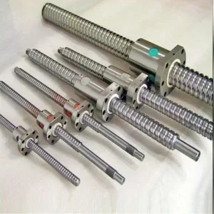
The fundamental operating principle of a CNC machine involves converting a digital model created in computer-aided design (CAD) software into a series of numerical commands called G-code via computer-aided manufacturing (CAM) software. These commands are then interpreted by the machine’s control unit and translated into mechanical movements. This process requires the harmonious operation of three main components: the mechanical structure, the electronic control system, and the software interface. The mechanical structure is critical for machining precision and repeatability. It is typically built on a frame composed of high-rigidity aluminum profiles, steel, or granite composite materials. Linear motion systems (linear guide rails and carriages) and precision drive mechanisms (ball screws or lead screws) ensure smooth and accurate movement along each axis. Ball screws offer low friction and high precision, while lead screws can be a more cost-effective alternative but may experience backlash issues. These drive systems are typically powered by stepper motors or servo motors. Stepper motors provide a cost-effective and sufficiently precise solution with open-loop control, whereas servo motors offer superior performance and precision with higher speed, torque, and feedback through closed-loop control.
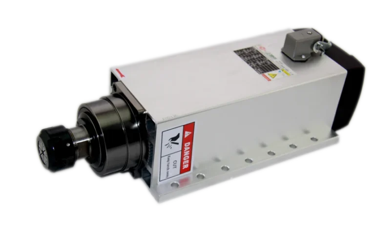
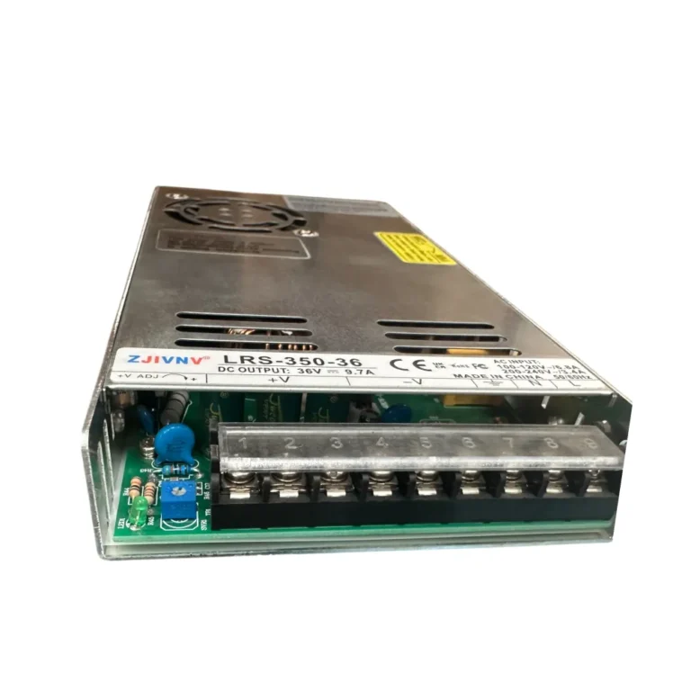
The electronic control system acts as the brain, converting G-code into motor movements. At the heart of this system is typically a microcontroller-based control board. Popular options include Arduino-based GRBL controllers (e.g., Uno and CNC Shield combination), Smoothieware (running on 32-bit processor boards), and more advanced industrial solutions like LinuxCNC (in conjunction with Mesa boards). These control boards process the G-code and send step and direction signals to motor drivers (A4988, DRV8825, TB6600, or external high-current drivers for stepper motors; dedicated servo drives for servo motors). The power supply must provide stable and sufficient current to all electronic components and motors. Spindle control is critically important, depending on the material to be machined and the tool type. For DC spindle motors, PWM (Pulse Width Modulation) based speed control is used, while for AC spindle motors, speed and torque control are provided by a Variable Frequency Drive (VFD). Safety is ensured by limit switches and emergency stop (E-stop) buttons; limit switches prevent the machine’s axes from exceeding their mechanical boundaries, while the E-stop instantly halts all movements, ensuring operator and machine safety.
On the software side, CAD (Computer-Aided Design) software (Fusion 360, SolidWorks, FreeCAD, etc.) is used for design. The created 3D models are transformed into machining strategies and toolpaths via CAM (Computer-Aided Manufacturing) software (Fusion 360 CAM, Estlcam, VCarve, ArtCAM, etc.), which then generates the G-code. Finally, the generated G-code is sent to the machine via a CNC Control Software (Universal Gcode Sender – UGS, Candle, LinuxCNC, Mach3/4, etc.) to initiate the machining process. These software typically display the machine’s position, monitor the G-code flow, and offer manual control capabilities. Precision and accuracy are the most critical factors determining a CNC machine’s performance. Mechanical backlash, motor step angle, driver micro-stepping, control board processing speed, and software calibration directly influence these factors. A successful CNC build is possible with careful selection, correct assembly, and meticulous calibration of these components.

FAQ
What are the primary benefits of building a custom CNC router machine?
Building your own CNC router machine offers significant cost savings compared to purchasing a pre-built industrial unit. It also provides invaluable experience in understanding the machine's mechanics, electronics, and software, allowing for deep customization to specific production needs and easier troubleshooting.
What mechanical components are essential for a high-performance CNC router?
Key mechanical components include a rigid frame (aluminum, steel, or granite composite), linear guide rails and carriages for precise motion, and drive mechanisms such as ball screws or lead screws. These ensure accuracy and repeatability in machining operations.
Which electronic components are critical for the CNC control system?
The electronic control system typically consists of a control board (like GRBL, Smoothieware, or LinuxCNC with Mesa cards), motor drivers (for stepper or servo motors), a stable power supply, and a VFD for AC spindle motor control. Limit switches and an E-stop button are crucial for safety.
What software is required for designing, generating G-code, and controlling a DIY CNC machine?
CAD software (e.g., Fusion 360, SolidWorks) is used for designing models. CAM software (e.g., Fusion 360 CAM, Estlcam) converts these models into G-code toolpaths. Finally, CNC control software (e.g., UGS, Mach3/4) sends the G-code to the machine for execution.
Should I choose stepper motors or servo motors for my industrial CNC router, and why?
For precise movement, servo motors are generally preferred over stepper motors in industrial applications due to their closed-loop control, higher speed, greater torque, and feedback capabilities, which ensure superior accuracy and performance.