No products in the cart.
Understanding Breakout Boards: Their Role in CNC Control Systems
Contents
Mermak CNC Technical Guide
Practical notes for CNC router, automation and industrial motion systems.
What is a Breakout Board? Its Function in CNC Control Systems
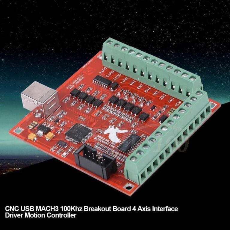
A breakout board is a critical interface card in CNC control systems that converts digital signals from a computer (typically from a parallel port, USB, or Ethernet) into isolated, amplified, and distributed signals required by motor drivers and other peripheral devices. Its primary function is to provide a secure, stable, and reliable communication pathway by protecting sensitive control signals from noise.
In industrial automation, particularly within CNC (Computer Numerical Control) systems, the breakout board acts as a bridge between the control computer and the machine’s components. It takes the typically low-power and noise-sensitive digital output signals from a computer and transforms them into more robust, isolated signals suitable for industrial standards. These signals are then sent to devices such as stepper motor drivers, servo motor drivers, limit switches, emergency stop (E-stop) buttons, spindle motor controls, and coolant pumps. The main purpose is to shield the computer’s sensitive electronic components from potential damage caused by the inductive loads of motors and ambient electrical noise, while ensuring a stable and error-free flow of control signals. Without a breakout board, directly connecting a computer to motor drivers could lead to signal degradation, incorrect commands, and even permanent damage to the computer. Therefore, a breakout board in CNC control systems is indispensable for safe, efficient, and long-lasting operation.
Principle of Operation and Technical Specifications
The working principle of a breakout board is based on three main functions: signal isolation, signal conditioning (buffering), and signal distribution. Digital signals from the control computer (typically 5V TTL level) are first physically separated from the computer’s control circuitry using optocouplers on the breakout board. Optocouplers transmit electrical signals from one circuit to another using light, creating galvanic isolation between the computer’s low-voltage control circuit and the machine’s high-power, noisy power circuit. This isolation prevents electrical noise and voltage spikes generated during motor switching from feeding back into the computer, thus protecting the computer and preserving signal integrity.
Following isolation, signals are typically passed through buffer circuits. These buffers amplify signal strength and reduce signal distortion, ensuring stable transmission even over longer cable runs. They also help adjust signals to the correct voltage and current levels. While passive breakout boards primarily provide pin outputs, active breakout boards include additional buffering, signal amplification, and sometimes logic functions (e.g., signal delay, inversion). Modern breakout boards can utilize USB or Ethernet interfaces to overcome the limitations of parallel ports. These interfaces offer advantages such as higher data transfer rates, more I/O pins, and reduced susceptibility to electrical noise. Ethernet-based solutions, in particular, are becoming increasingly popular in industrial applications due to their stable communication capabilities over long distances and real-time control potential.
Signal distribution involves routing incoming signals to multiple output pins and transmitting them in the appropriate format to different components like motor drivers and limit switches. For instance, the step and direction signals for an axis are routed through the breakout board to the respective stepper motor driver. Similarly, feedback signals from an E-stop button or limit switches are safely transmitted to the computer via the breakout board. These boards typically feature various input/output (I/O) pins, allowing users to connect different sensors, actuators, and control elements according to their machine’s requirements. Power supply integration is also a key feature; many breakout boards can provide different voltage outputs, such as 5V for the control circuit and 12V or 24V for peripheral components, simplifying the system’s overall power management and reducing reliance on external power supplies.
| Parameter | Value/Description |
|---|---|
| Input Interface | Parallel Port (LPT), USB, Ethernet |
| Output Channels | 3, 4, 5, 6-axis control (Step/Dir), Spindle, Coolant, Relay Outputs |
| Isolation Type | Opto-isolation (Galvanic Isolation) |
| Input Voltage | 5V – 24V DC (varies by operating voltage) |
| Signal Levels | TTL (5V), 3.3V compatible |
| Supported Software | Mach3, Mach4, LinuxCNC, GRBL (for customized boards) |
| Safety Features | Emergency Stop (E-Stop) Input, Limit Switch Inputs |
Key Considerations in Practice
- Correct Board Selection and Compatibility: Selecting the appropriate breakout board for each CNC control system is crucial. Ensure the board meets the requirements of the motor drivers (stepper or servo), the number of axes, the spindle motor control type (analog 0-10V, PWM, relay), and the software (e.g., Mach3, LinuxCNC). For parallel port-based boards, computer compatibility (a true parallel port or PCI-E card) is critical. USB and Ethernet solutions offer broader compatibility and better performance.
- Cabling and Noise Management: Electrical noise is inevitable in industrial environments. Signal cables (especially for step/direction and limit switches) should be shielded and routed separately from power cables. Proper grounding techniques must be employed to minimize noise, ensuring all components share a common ground point. Cable routing should be designed to minimize electromagnetic interference (EMI) and radio frequency interference (RFI).
- Power Supply Quality and Sufficiency: Ensure that the breakout board and all connected peripherals (motor drivers, sensors) are powered by a stable and adequate power supply. Low-quality or insufficient power supplies can lead to signal distortions, unstable operation, and system failures. Most active breakout boards require a DC voltage (typically 12V or 24V); this supply must be clean and free of fluctuations.
- Importance of Grounding and Isolation: One of the most critical functions of breakout boards is isolation. For this isolation to work effectively, the system’s overall grounding scheme must be correctly designed. Establishing the right separation or connection between the computer’s ground and the machine’s power ground is vital to prevent ground loops and ensure safety. Verify that optocouplers are functioning correctly and providing high-voltage protection.
- Software Configuration and Calibration: All input and output pins on the breakout board must be correctly configured within the CNC control software (Mach3, LinuxCNC, etc.). Correct pin assignments are needed for each axis’s step/direction pins, limit switches, E-stop, and other auxiliary functions. Motor calibration (steps/mm or steps/inch) and acceleration/deceleration settings directly impact the machine’s precision and performance. Incorrect configuration can lead to machine malfunction or potential hazards.
- Thermal Management and Environmental Conditions: Active breakout boards may contain integrated circuits that generate heat during operation. In enclosed control cabinets or high ambient temperatures, adequate ventilation or heatsinks may be necessary to prevent overheating and ensure reliable performance.
By understanding and correctly implementing these considerations, you can ensure your CNC machine operates reliably and efficiently with its breakout board.
For robust CNC control solutions, explore Mermak CNC’s range of products. Request a quote on WhatsApp to discuss your specific industrial automation needs.
Related product categories: Uncategorized · 0.75 Kw Variable Frequency Drives · 06B-2 Roller Chain Sprocket