No products in the cart.
Braking Resistor Selection and Ohm/Watt Calculation in Inverters (VFDs)

Contents
- Braking Resistor Selection and Ohm/Watt Calculation in Inverters (VFDs): Introduction and Technical Analysis In industrial automation systems, particularly for controlling high-inertia loads or applications requiring rapid stops, Variable Frequency Drives (VFDs), also known as inverters, are indispensable for precisely managing motor speed and torque. However, energy management during motor braking or stopping presents a critical engineering challenge for system safety, efficiency, and longevity. This is precisely where braking resistors come into play. Braking resistors are passive electronic components designed to dissipate regenerative energy as heat, preventing the VFD’s DC bus voltage from rising when the motor enters generator mode. This technical article and field guide aim to provide a comprehensive overview of braking resistor selection in inverters, Ohm and Watt value calculations, field considerations, common problems, and solutions. Our goal is to equip industrial automation professionals with the necessary theoretical and practical knowledge for the correct integration of this critical component. Operating Principle and Technical Data for Braking Resistor Selection and Ohm/Watt Calculation in Inverters (VFDs)
- Calculating Resistance (Ohm) Value
- Calculating Power (Watt) Value
- Field Considerations for Braking Resistor Selection and Ohm/Watt Calculation in Inverters (VFDs)
- Common Problems and Solutions in Braking Resistor Selection and Ohm/Watt Calculation in Inverters (VFDs)
- Conclusion and Expert Advice on Braking Resistor Selection and Ohm/Watt Calculation in Inverters (VFDs)
- FAQ
Braking Resistor Selection and Ohm/Watt Calculation in Inverters (VFDs): Introduction and Technical Analysis
In industrial automation systems, particularly for controlling high-inertia loads or applications requiring rapid stops, Variable Frequency Drives (VFDs), also known as inverters, are indispensable for precisely managing motor speed and torque. However, energy management during motor braking or stopping presents a critical engineering challenge for system safety, efficiency, and longevity. This is precisely where braking resistors come into play. Braking resistors are passive electronic components designed to dissipate regenerative energy as heat, preventing the VFD’s DC bus voltage from rising when the motor enters generator mode. This technical article and field guide aim to provide a comprehensive overview of braking resistor selection in inverters, Ohm and Watt value calculations, field considerations, common problems, and solutions. Our goal is to equip industrial automation professionals with the necessary theoretical and practical knowledge for the correct integration of this critical component.
Operating Principle and Technical Data for Braking Resistor Selection and Ohm/Watt Calculation in Inverters (VFDs)
When an electric motor attempts to decelerate or stop the load it drives, mechanical energy is converted into electrical energy. This phenomenon is particularly pronounced in applications such as elevators, cranes, conveyors, centrifuges, or high-inertia fans. During this process, the motor acts like a generator, feeding current back towards the VFD’s DC bus. This regenerative current causes the DC bus voltage to rise above the inverter’s permissible maximum operating voltage. This condition is termed a DC Bus Overvoltage Fault and causes the inverter to trip (shut down) to protect itself. Such undesirable shutdowns can lead to production losses, equipment damage, and serious safety risks.
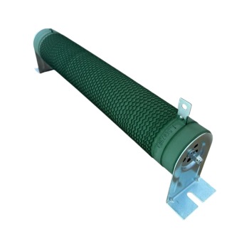
A braking resistor is designed to safely dissipate this regenerative energy. A braking chopper or brake unit, located either within the inverter or as an external unit, automatically activates when the DC bus voltage reaches a certain threshold. This chopper switches the braking resistor in parallel with the DC bus, ensuring that the excess energy is dissipated as heat across the resistor. This keeps the DC bus voltage within safe limits and ensures continuous operation of the inverter.
Calculating Resistance (Ohm) Value
One of the most critical steps in selecting a braking resistor is determining the correct Ohm value. The resistance value must not be lower than the minimum resistance value specified by the inverter’s braking chopper. Otherwise, the chopper circuit may be overloaded with excessive current and damaged. The resistance value also affects braking performance; a resistance that is too high may be insufficient to dissipate energy quickly enough, failing to prevent an overvoltage fault.
Fundamentally, the resistance value can be calculated using the following formula:
R_min = V_dc_peak^2 / P_peak
- R_min: Required minimum resistance value (Ohms).
- V_dc_peak: DC bus voltage at which the braking chopper activates (Volts). This value is specified in the inverter’s technical documentation (e.g., approximately 750-800V for a 400V mains supply).
- P_peak: Maximum instantaneous power to be dissipated during braking (Watts). This is typically a certain multiple of the motor’s nominal power or the maximum braking power required by the application.
Most inverter manufacturers specify recommended minimum resistance values or a range in their technical catalogs, based on motor power. These values are usually determined by the current capacity of the braking transistor (IGBT) inside the inverter. These catalog values should be used as a starting point and verified with detailed calculations specific to the application.

Calculating Power (Watt) Value
The power rating (Watt) of a resistor indicates the average amount of heat the resistor can safely dissipate over a specific period. This is directly related to the frequency and duration of the braking cycle. The Watt value of a braking resistor should reflect not only its instantaneous maximum power but also its thermal capacity and cooling capability. An incorrectly chosen Watt value can lead to resistor overheating, degradation, or fire risk.
Power calculation typically relies on two main factors: average braking power (P_avg) and peak braking power (P_peak).
1. Average Braking Power (P_avg) Calculation:
This is the average power dissipated across the resistor during a braking cycle. The following formula or its derivatives are commonly used:
P_avg = P_braking_peak * (t_braking / t_cycle)
- P_braking_peak: Instantaneous peak power generated across the resistor during braking (Watts). This can be 100% or more of the motor’s nominal power, varying by application.
- t_braking: Active braking time per braking event (seconds).
- t_cycle: Total duration of one complete operating cycle (seconds). This includes the entire time the motor accelerates, runs at constant speed, and brakes.
Alternatively, a kinetic energy-based calculation can provide more accurate results:
E_kinetic = 0.5 * J * (ω1^2 – ω2^2) (Joules)
Where;
- J: Moment of inertia of the entire rotating mass (kg·m²).
- ω1: Initial angular velocity (rad/s).
- ω2: Final angular velocity (rad/s).
Then, the average braking power:
P_avg = E_kinetic / t_cycle (Watts)
Here, t_cycle is the total cycle time. If average power is desired only over the braking time, the formula P_avg = E_kinetic / t_braking can be used, but in this case, the resistor’s thermal capacity and cooling time must be considered more carefully.
2. Peak Braking Power (P_peak) Calculation:
This is the highest instantaneous power generated across the resistor during braking. The resistor must be able to withstand this peak power for a short duration. Generally, a peak power of 100% to 150% of the motor’s nominal power is considered. In some applications (e.g., emergency stops), this ratio can be higher.
The Watt value of the selected resistor should be at least 20-30% higher than the calculated P_avg value, and the resistor’s capacity to handle the P_peak value for short durations must be checked. Resistor manufacturers provide datasheets specifying the instantaneous overload capacities of their resistors (e.g., 10 times nominal power for 10 seconds).
| Parameter | Value/Description |
|---|---|
| DC Bus Voltage (Vdc) | Typically 700-800V for 400V mains (chopper activation threshold) |
| Minimum Resistance (Ohm) | Minimum value recommended by inverter manufacturer (e.g., 10-15 Ohm for 37 kW motor) |
| Braking Time (t_braking) | Time for load to decelerate and stop (e.g., 5 seconds) |
| Cycle Time (t_cycle) | Total duration of one complete operating cycle (e.g., 60 seconds) |
| Motor Power (kW) | Motor’s nominal power (e.g., 37 kW) |
| Required Average Braking Power (Watt) | Calculated average dissipation power (e.g., 3000W – 5000W) |
| Resistor Material | Wirewound, metal film, grid type – varies by application |
| Protection Class (IP) | IP20 (open), IP54 (enclosed), IP65 (very dusty/humid) depending on environmental conditions |
Field Considerations for Braking Resistor Selection and Ohm/Watt Calculation in Inverters (VFDs)
- Resistor Placement and Cooling: Braking resistors generate significant heat during operation. Therefore, resistor placement is critically important. The resistor should be mounted in a well-ventilated area, kept at a sufficient distance from other heat-sensitive components (PLC, contactors, cable trays, etc.). Objects that could obstruct airflow should be avoided, and forced cooling (fan) should be used if necessary. If mounted inside enclosed panels, the panel’s thermal management (ventilation holes, filtered fans, exhaust fans) should be re-evaluated. The resistor’s enclosure should be designed to prevent touch hazards for personnel or marked with warning labels.
- Cable Selection and Connection: The cross-section of the cable between the braking resistor and the inverter must be appropriate for the high current that will flow during braking. Cable length can affect resistance value by increasing inductance and can cause voltage drops. The shortest possible cable with the correct cross-section should be used. Connection points must be tight and secure to prevent loosening and withstand high temperatures. For EMC (Electromagnetic Compatibility) purposes, shielded cable is recommended, and the shield should be grounded, especially when running near signal cables.
- VFD Parameter Settings: The braking chopper parameters of the inverter must be set correctly. These parameters typically include values such as “DC bus overvoltage threshold,” “braking chopper activation voltage,” and “braking chopper duty cycle.” Incorrect settings can cause the resistor to activate unnecessarily or insufficiently. For example, if the activation voltage is set too high, the resistor may not dissipate enough energy before the inverter trips with an overvoltage fault.
- Thermal Protection: Large braking resistors may be equipped with internal thermostats or thermal fuses to prevent overheating. These protection elements should send a fault signal to the inverter, stopping the system when the resistor reaches a critical temperature. This is vital for protecting both the resistor and surrounding equipment. The thermal protection element’s connection should be checked periodically.
- Mechanical Durability and Vibration: Industrial environments can often be vibratory. The resistor must be mounted securely to withstand these vibrations. Fasteners (screws, nuts) should be of a type that will not loosen over time and should be checked regularly.

Common Problems and Solutions in Braking Resistor Selection and Ohm/Watt Calculation in Inverters (VFDs)
The main problems encountered in braking resistor applications typically arise from incorrect selection, faulty installation, or environmental factors. Here are some common problems and suggested solutions:
- Problem: The inverter continuously displays a “DC Bus Overvoltage” fault.
Causes:
- The selected braking resistor’s Ohm value is too high. In this case, the resistor cannot draw enough current and cannot dissipate regenerative energy quickly.
- The braking resistor’s Watt value is insufficient. The resistor cannot handle the average or peak power generated during the braking cycle, leading to overheating, increased resistance, or an open circuit.
- The braking chopper is faulty or not operating.
- The cable connection between the braking resistor and the inverter is loose, broken, or has an insufficient cross-section.
- The VFD’s braking chopper activation voltage is incorrectly set.
Solutions:
- Recalculate the resistor Ohm value to be close to, but never below, the minimum value recommended by the inverter manufacturer, and replace it with an appropriate resistor.
- Recalculate the Watt value based on the braking cycle and motor power, and use a resistor with a higher Watt rating. Check the resistor’s thermal capacity.
- Test the braking chopper’s operation (if it’s an external unit, check its power supply and control signals; if integrated, check the inverter’s status).
- Check cable connections, tighten them, and ensure the cable cross-section is sufficient.
- Check the braking chopper activation voltage in the VFD parameters and set it to the manufacturer’s recommended value.
- Problem: The braking resistor overheats excessively, melts, or burns out.
Causes:
- The resistor’s Watt value is too low for the average braking power required by the application.
- The resistor’s placement has insufficient ventilation, hindering heat dissipation.
- The braking cycle is more frequent or longer than calculated.
- The internal thermal protection mechanism of the resistor is faulty or not connected.
Solutions:
- Recalculate the Watt value considering the application’s actual braking cycle and duration, and replace it with a resistor with a higher Watt rating. Remember to add a safety margin.
- Improve airflow around the resistor; if necessary, add fan cooling or mount it in a larger area.
- Review the application’s operating profile and evaluate if it’s possible to reduce the braking time or frequency.
- Check the resistor’s thermal protection sensor and its connection; replace or connect it correctly to the system if necessary.
- Problem: The braking resistor has a short lifespan or frequently fails.
Causes:
- The resistor quality is low or not suitable for industrial conditions (e.g., vibration, humidity, dust).
- The resistor is operated beyond its design limits (both Ohm and Watt).
- Loose connections or corrosion in cable connections cause resistor failure.
Solutions:
- Use a higher-quality resistor specifically designed for industrial applications and with an appropriate IP protection class.
- Ensure that the resistor’s Ohm and Watt values meet the application requirements and include a sufficient safety margin.
- Establish periodic maintenance routines to check, tighten, and clean connection points.
Conclusion and Expert Advice on Braking Resistor Selection and Ohm/Watt Calculation in Inverters (VFDs)
While braking resistor selection and calculation in inverters may seem like a simple component task, it is a critical engineering discipline for the performance, safety, and longevity of industrial automation systems. Determining the correct Ohm and Watt values not only prevents the inverter from issuing a “DC Bus Overvoltage” fault but also ensures the motor stops quickly and safely, increasing production efficiency and extending equipment life. Our field experience shows that many failures and production downtimes result from incorrect braking resistor selection, inadequate cooling, or faulty installation. Therefore, it is vital to thoroughly analyze the unique dynamics of each application (load inertia, braking time, cycle frequency, environmental conditions) and select the resistor accordingly. While inverter manufacturers’ catalog data and calculation tools provide a valuable starting point, seeking support from experienced automation engineers or system integrators for complex or critical applications is the smartest way to minimize potential risks. It should be remembered that a correct selection and installation at the outset will save long-term operating costs and significantly contribute to the continuous operation of the system. In the future, although regenerative braking systems will become more common, braking resistors will continue to be an indispensable solution in industrial applications due to their cost-effectiveness and simplicity. Therefore, continuously updating knowledge on this subject is essential to maintain competitiveness in the industry.
FAQ
What is a braking resistor and why is it used with VFDs?
A braking resistor is a passive electronic component used with Variable Frequency Drives (VFDs) to dissipate excess regenerative energy as heat. This prevents the DC bus voltage in the VFD from exceeding safe limits when a motor, particularly one driving a high-inertia load, decelerates or stops and acts as a generator.
Why is the correct Ohm value important for a braking resistor?
The Ohm value of a braking resistor is critical. If it's too high, the resistor won't draw enough current to dissipate regenerative energy effectively, leading to DC bus overvoltage faults. If it's too low, it can overload and damage the VFD's internal braking chopper circuit. Always adhere to the minimum resistance value specified by the VFD manufacturer.
What is the significance of the Watt value in braking resistor selection?
The Watt value indicates the average power a resistor can safely dissipate as heat over time. An insufficient Watt rating will cause the resistor to overheat, potentially leading to damage, fire risk, or premature failure. It must be selected based on the average and peak braking power requirements of the application, often with a safety margin.
What factors should be considered when calculating the Ohm and Watt values for a braking resistor?
Key factors include load inertia, braking time, braking cycle frequency, motor power, and the VFD's DC bus overvoltage threshold. Environmental conditions like temperature, humidity, and vibration also influence the resistor's construction and IP rating.
What are common problems with braking resistors and how can they be solved?
Common issues include continuous DC bus overvoltage faults (often due to incorrect Ohm or Watt values, or a faulty chopper), excessive resistor overheating (due to insufficient Watt rating or poor ventilation), and short resistor lifespan (due to low quality, operation beyond limits, or poor connections). Solutions involve recalculating values, improving ventilation, checking VFD parameters, and ensuring high-quality components and secure connections.