



































































































































Best Free and Open-Source CNC Drawing Software for Industrial Use
📑 Table of contents (Click to open)
Introduction and Technical Analysis
The industrial automation sector is in a continuous state of evolution, driven by the pursuit of efficiency, precision, and cost-effectiveness in manufacturing processes. A cornerstone of this evolution lies in computer-aided design (CAD) and computer-aided manufacturing (CAM) software. Specifically, drawing and toolpath generation programs for CNC (Computer Numerical Control) machines are indispensable components of modern manufacturing. For small and medium-sized enterprises (SMEs), new entrepreneurs, and educational institutions, the high costs associated with commercial software often present a significant barrier. In this context, free and open-source CNC drawing programs enhance accessibility, contributing greatly to local industrial development. This field guide and technical article provide a technical analysis of such programs for industrial automation professionals, explaining their operating principles and offering expert advice on their practical applications.
CNC drawing programs can fundamentally be divided into two main categories: CAD (Computer-Aided Design) and CAM (Computer-Aided Manufacturing). CAD software is used to perform the geometric modeling of a product, meaning the 2-dimensional (2D) or 3-dimensional (3D) design of a part or component. These designs are dimensioned according to engineering principles, tolerances are assigned, and material properties are defined. CAM software, on the other hand, generates numerical command sequences, known as G-code, from the CAD model, which the CNC machine can understand. These G-codes include critical parameters such as tool movement path, spindle speed, feed rate, and cutting depth. In the world of automation, these two stages often complement each other through integrated software or data transfer between different software. Free solutions typically offer either CAD or CAM capabilities exclusively, or they combine both at a basic level. Multilingual support, especially for accurate understanding of technical terms and ease of user interface, is a critical advantage for users, as it shortens the learning curve and prevents costly production downtimes caused by incorrect usage.
In the industrial automation sector, precision and repeatability are paramount. Therefore, the reliability of the software used, the quality of its output, and its compliance with standards are of great importance. While free software may have some limitations compared to its commercial counterparts, when chosen correctly and used with an expert approach, it can deliver sufficient performance for many applications. Especially for prototyping, education, small-scale production, and specific niche applications, these solutions can provide a competitive advantage by reducing investment costs. This article aims to provide the necessary technical information and practical recommendations to maximize this potential.
Operating Principles and Technical Data
The operating principle of CNC drawing programs is based on managing the process of transforming a digital design into a physical product. This process typically consists of three main steps: design (CAD), toolpath generation (CAM), and G-code production. In the CAD stage, users define the geometry of the part by creating 2D sketches or 3D models. These models are dimensioned and detailed according to technical drawing standards. Subsequently, in the CAM stage, this CAD model is taken, and toolpaths are calculated by inputting parameters such as the type of material to be processed, the geometry of the cutting tool to be used, and the spindle and feed rates. Toolpaths determine how the cutting tool will process the material, at what depth, and in what direction it will move. As a result of these calculations, G-code (geometric code) and M-code (machine function code) sequences are generated, which the CNC machine can directly understand. G-codes control the tool’s position (X, Y, Z coordinates), type of movement (linear, circular), feed rate, and spindle speed; while M-codes manage auxiliary functions such as turning coolant on/off and tool changes.
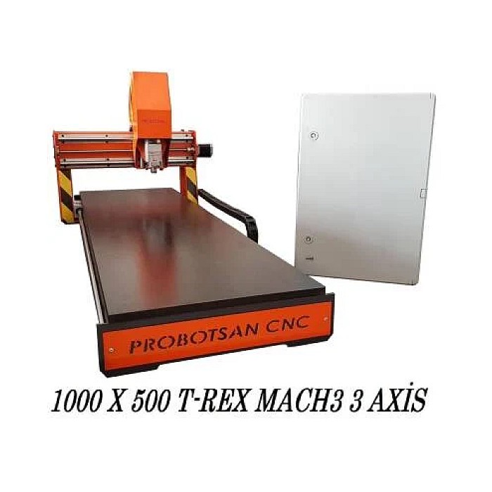
CNC machines used in industrial automation applications vary widely. Milling machines (CNC Router, CNC Vertical Machining Center), lathes, laser cutting machines, plasma cutting machines, waterjet cutting machines, and 3D printers fall into this category. Each machine type has its own unique operating principle and, consequently, different CAM software requirements. For example, while 2D vector drawings (DXF, SVG) are sufficient for a laser cutting machine, a comprehensive 3D modeling and 3-axis, 4-axis, or 5-axis toolpath calculation capable CAM software is required for a milling machine processing a complex 3D part. Free software generally offers more suitable solutions for 2D applications (laser, plasma cutting) or simple 3D milling. For more complex 3D machining or multi-axis operations, the in-depth features of commercial software may be needed, but for basic prototyping and educational uses, free alternatives are quite sufficient.
The technical data specifications and capabilities of a CNC drawing program determine its suitability for industrial use. Particularly, file format support (such as DXF, DWG, SVG, STL, STEP, IGES) is critically important for data exchange with other CAD/CAM software. G-code editing and simulation capabilities are indispensable for checking the accuracy of the generated code and for detecting potential collisions or errors in advance. Post-processor flexibility ensures that the software can generate G-code compatible with different brands and models of CNC control units; because each CNC control unit (Fanuc, Siemens, Mach3, GRBL, etc.) may interpret G-codes slightly differently. Multilingual support, especially for operators and engineers with varying levels of technical training, is a great advantage in terms of ease of use and reducing error rates. Considering the general structure of free software, active community support and online resources often play a significant role in learning the software and solving encountered problems. The selection and implementation of such software should be carefully made according to the enterprise’s existing machine park, production needs, and the competence of its technical personnel.
| Parameter | Value/Description |
|---|---|
| Software Type | CAD (2D/3D Modeling) and/or CAM (Toolpath Generation) |
| Supported Machine Types | CNC Router, Laser Cutting, Plasma Cutting, 3D Printers (Typically 2.5 axis) |
| 2D/3D Capability | Strong 2D, basic or intermediate 3D capabilities in most free software |
| G-Code Generation | General G-code support for popular controllers like GRBL, Mach3, LinuxCNC |
| Multilingual Support | May exist with community translations or built-in support, quality may vary |
| File Format Support | DXF, SVG, STL (import/export), OBJ, STEP (limited import) |
| Community/Support | Active forums, wiki pages, and user groups in open-source projects |
| License Type | Open-source licenses like GNU GPL, MIT License, or freemium models |
Field Considerations
- Machine and Controller Compatibility: Each CNC machine has its own specific control unit (e.g., GRBL, Mach3, LinuxCNC, Fanuc, Siemens) and these units have particular G-code dialects. It is vital that the G-code generated by a free drawing program can be correctly interpreted by your existing CNC machine’s controller. The software usually includes post-processor options for different controllers. Correct configuration of these options, or if necessary, the creation of a custom post-processor, is a critical step for error-free production. Incompatibilities can lead to tool collisions, production of incorrectly sized parts, or unexpected machine behavior.
- Learning Curve and Documentation: Free software can often have a steeper learning curve compared to its commercial counterparts. The availability of comprehensive and up-to-date documentation significantly eases this process. Investing in training for personnel who will use the software ensures that the time spent initially translates into operational efficiency later on. Online tutorials, YouTube guides, and community forums are important resources in the learning process. Before transitioning to new software, it is necessary to realistically assess how quickly your team can effectively use it.
- Community Support and Updates: One of the biggest advantages of free and open-source software is that it often has an active and helpful community. These communities are invaluable for finding quick solutions to encountered problems, learning about new features, and even contributing to the software’s development. However, one should not expect guaranteed technical support services as with commercial software. Regular software updates are important for bug fixes and the addition of new features. Software that has not been updated for a long time may experience security vulnerabilities or compatibility issues with modern operating systems.
- Licensing and Commercial Use Terms: The word “free” does not always mean “free for commercial use.” Some free software allows only personal or educational use, while others have open-source licenses (e.g., GPL, MIT) that also permit commercial use. Before using the software for commercial production in an industrial automation environment, it is absolutely necessary to carefully review the license terms and ensure legal compliance. License violations can lead to serious legal and financial consequences for businesses.
- Performance and Hardware Requirements: Especially when working with complex 3D models or performing intensive toolpath calculations, the software’s performance and how efficiently it uses system resources are important. Some free software may be less optimized than its commercial counterparts and may require more powerful hardware. Checking whether your existing computer hardware meets the requirements of the selected software ensures that the software runs efficiently and does not create bottlenecks in your workflow. This becomes more pronounced when working with large files or performing simulations.
- Feature Set and Limitations: Free software generally does not have all the advanced features offered by commercial software. For example, multi-axis machining (4 or 5 axes), complex surface machining strategies, or integrated simulation capabilities may be limited. It is important to clearly define your business’s current and future production needs and evaluate whether the chosen free software meets these needs. Software that seems sufficient at first may become inadequate as operations grow or become more complex. Therefore, it would be beneficial to consider whether the software has upgrade or add-on options.
Common Problems and Solutions
When using free CNC drawing programs in an industrial automation environment, some common problems that may be encountered and practical solutions are listed below:
1. G-Code Errors or Machine Incompatibilities:
- Problem: The G-code generated by the software is either not read at all by the CNC machine or is misinterpreted, leading to incorrect movements or stoppages. The machine controller may issue warnings such as “undefined command” or “syntax error.”
- Solution: This situation is usually caused by an incorrectly or incompletely configured post-processor. First, check the software’s post-processor settings and select the one appropriate for your machine’s control unit (GRBL, Mach3, Fanuc, etc.). If there is no suitable post-processor, look for information on creating a custom post-processor or editing an existing one in the software’s community forums or documentation. Running the machine with a very simple test G-code (e.g., drawing just a square) in initial attempts can help narrow down the source of the problem. In some cases, compatibility can be achieved by manually editing the G-code (e.g., changing line endings, spaces, or specific commands).
2. Performance Issues and Slow Operation:
- Problem: The software slows down, freezes, or crashes, especially with complex 3D models or during intensive toolpath calculations.
- Solution: This usually results from insufficient hardware (processor, RAM, graphics card) or lack of software optimization. First, ensure your computer meets the software’s minimum system requirements. If necessary, increase RAM or use a computer with a more powerful processor. In the software’s settings, check for performance improvement options such as reducing graphic quality, optimizing cache settings, or multi-core usage. Processing large models by dividing them into smaller, manageable parts can also be a solution. Closing unnecessary programs running in the background will also free up system resources.
3. File Transfer and Compatibility Problems:
- Problem: Files such as DXF, STL, or STEP transferred from different CAD software do not open correctly in the program, show geometric distortions, or come with missing data.
- Solution: Version incompatibilities of file formats or differences in export/import settings can cause this problem. If possible, try saving the file in an older format version in the exporting software (e.g., DXF 2000). For STL files, ensure that the triangle density (mesh density) settings are correct; too low density can lead to loss of detail, while too high density can increase file size and cause performance issues. If your program supports neutral formats like STEP or IGES, try to minimize data loss by using these formats. In some cases, using a third-party file converter software can also be beneficial.
4. Toolpath Calculation Errors or Incorrect Machining:
- Problem: The generated toolpaths are not as expected, the cutting tool passes through incorrect areas, over- or under-machines the material, or poses a risk of collision.
- Solution: This usually stems from incorrectly defined tool parameters (diameter, length, corner radius), incorrect machining strategy selection, faulty stock definition, or missing tool compensation settings. Ensure all parameters in the tool library match your physical tools. Carefully review machining strategies (roughing, finishing, contouring, pocketing, etc.) and select the most appropriate one for your application. Especially in 2D cutting, correct setting of tool compensation (right, left, center) is critical. Use the simulation feature found in most CAM software to check toolpaths in a virtual environment and detect potential errors before production. Simulation is the most effective tool to avoid real production costs and potential machine damage.
5. Character Issues and Interface Problems:
- Problem: Special characters in the software interface are displayed incorrectly, or problems occur when these characters are used in file names.
- Solution: This usually results from the character encoding settings of the software or operating system. Ensure that multilingual or Unicode (UTF-8) support is enabled in the software’s language settings. Make sure your operating system’s regional settings and default language are correctly configured. Using the English alphabet and numbers instead of special characters in file names and folder paths can prevent compatibility issues, especially on older or specific systems. In some cases, updating to a newer version of the software can resolve such character encoding issues.
Expert Advice
The use of free and open-source CNC drawing programs in the industrial automation sector offers a cost-effective and accessible solution, especially for SMEs, educational institutions, and prototyping companies. The technical analyses, operating principles, field-focused considerations, and solutions to common problems discussed in this article serve as a comprehensive guide to maximize the potential of such software and overcome potential challenges. It should be remembered that the label “free” does not always mean “complete” or “problem-free”; however, with correct expectations and a conscious approach, these tools can add significant value to your industrial processes.
As an expert, my advice is to first thoroughly analyze your business’s current and future needs when selecting any free CNC drawing program. What types of CNC machines do you have? What types of parts do you produce (2D cutting, 2.5D milling, 3D machining)? What file formats do you work with? The answers to these questions will guide you in determining the most suitable software. Be sure to evaluate the quality of multilingual support, the activity of community support, and the accessibility of documentation. Starting with simple projects to master the software and workflow will help you gain confidence and experience for transitioning to more complex projects. Additionally, it is critically important to carefully read the licensing terms and ensure legal compliance before using any software for commercial purposes.
Industrial automation is a dynamic field, and technological developments are progressing rapidly. Therefore, it is important that the software you choose remains current and can adapt to your evolving needs over time. The potential for continuous updates and community contributions in open-source projects can offer a great advantage in this regard. Remember that software is just a tool; true success is achieved through the knowledge, experience, and problem-solving abilities of the operator and engineer. By intelligently using free tools, you can achieve precision, efficiency, and innovation in your production processes without being dependent on high-cost commercial software. Being open to continuous learning and experimenting with new technologies will give you an edge in this competitive sector.
Request a Quote on WhatsApp
FAQ
What is free CNC drawing software and how does it benefit industrial users?
Free CNC drawing software, often referred to as CAD/CAM software, allows industrial users to design 2D or 3D parts (CAD) and then generate the necessary G-code toolpaths (CAM) for CNC machines like CNC routers, laser cutters, or plasma cutters. This enables cost-effective prototyping and production.
What are the essential features to consider when choosing free CNC drawing software for industrial applications?
Key features to look for include strong 2D and basic 3D modeling capabilities, G-code generation for common CNC controllers (e.g., GRBL, Mach3), support for essential file formats (DXF, SVG, STL), and an active community for support and updates. Post-processor flexibility for various machine types is also crucial.
What are the common problems encountered with free CNC drawing software and how can they be resolved?
Common challenges include G-code incompatibility with specific CNC machine controllers, performance issues with complex models due to hardware limitations, file transfer problems between different software, and errors in toolpath calculations. These can often be resolved by correctly configuring post-processors, optimizing hardware, ensuring proper file format versions, and utilizing simulation features.
Can free CNC drawing software be used for commercial industrial production?
While many free software options are open-source and permit commercial use, it's vital to carefully review the specific license terms (e.g., GPL, MIT) for each program. Some free versions might be restricted to personal or educational use only. Always ensure legal compliance before using any software for commercial production.
How can I ensure compatibility between free CNC software and my industrial CNC router machine?
To ensure compatibility, verify that the software's post-processor supports your CNC machine's control unit (e.g., Fanuc, Siemens, Mach3, GRBL). Test with simple G-code programs first. If necessary, you may need to customize or create a specific post-processor to match your machine's G-code dialect.


