No products in the cart.
Mach3 Setup and Configuration: A Comprehensive Guide for Industrial CNC
Contents
- Mach3 Setup and Configuration: A Field Guide and Technical Article In the realm of industrial automation, particularly in the control of computer numerical control (CNC) systems, the role of software is paramount. In this context, Mach3 stands as a popular CNC control software utilized across a wide spectrum of applications, from hobbyist and small-scale industrial setups to extensive retrofit projects. This guide meticulously details the correct and efficient installation and configuration of Mach3, along with providing solutions for potential field issues, all from the perspective of experts in the industrial automation sector. Our objective is to furnish operators and engineers with the knowledge base required to extract maximum efficiency from Mach3-based systems. Introduction and Technical Analysis
- Operating Principle and Technical Data
- Field Considerations
- Common Problems and Solutions
- Expert Advice
- FAQ
Mach3 Setup and Configuration: A Field Guide and Technical Article
In the realm of industrial automation, particularly in the control of computer numerical control (CNC) systems, the role of software is paramount. In this context, Mach3 stands as a popular CNC control software utilized across a wide spectrum of applications, from hobbyist and small-scale industrial setups to extensive retrofit projects. This guide meticulously details the correct and efficient installation and configuration of Mach3, along with providing solutions for potential field issues, all from the perspective of experts in the industrial automation sector. Our objective is to furnish operators and engineers with the knowledge base required to extract maximum efficiency from Mach3-based systems.
Introduction and Technical Analysis
Mach3, developed by ArtSoft, is a CNC control software that operates on the Windows operating system. Fundamentally, it translates G-code defined motion commands into physical axis movements by controlling stepper motor drivers or servo drives via the computer’s parallel port or an external motion controller. This software is applicable to various CNC machines, including milling machines, lathes, plasma cutters, industrial CNC router machines, and 3D printers. One of Mach3’s significant advantages lies in its flexibility and extensive configuration options. This flexibility enables the seamless integration of systems with diverse mechanical configurations and electronic components. However, this advantage necessitates a precise and careful installation and setup process. Incorrect configuration can lead to diminished machine performance, loss of accuracy, and even safety hazards.
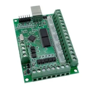
Reasons for Mach3’s preference in the industry include its relatively low cost, extensive user base, community support, and compatibility with various hardware (especially older parallel port-based systems). However, compatibility issues between modern PC hardware and operating systems with the parallel port have led to the widespread adoption of external USB/Ethernet-based motion controllers like SmoothStepper or UC100. These controllers enhance Mach3’s real-time performance, ensuring more stable and high-speed operations. During the installation process, factors such as software license status, the type of controller to be used, and the mechanical specifications of the machine must be meticulously evaluated from the outset. This evaluation plays a pivotal role in preventing potential integration and performance issues in the future.
Operating Principle and Technical Data
Mach3’s operating principle begins with interpreting G-code (Geometric Code), a standard programming language. The machining paths of a part designed in CAD/CAM software are converted into G-code. Mach3 reads this G-code file, analyzes each command, and generates the necessary step and direction signals for the respective axes to move at a specific speed and acceleration. These signals are transmitted to stepper motor drivers via the computer’s parallel port or an external motion controller. The stepper motor drivers apply current to the motor windings according to the received signals, causing the motor to rotate at specific angles. This rotational movement drives the machine’s axes through mechanical transmission elements (screws, belts, gears).
Since Mach3 does not run on a real-time operating system, delays (latency) inherent in Windows are critically important. These delays can cause step losses or vibrations, especially in high-speed and precision applications. Therefore, it is recommended to optimize the computer running Mach3 (disabling unnecessary services, minimizing background applications) or use an external motion controller. External controllers take over the task of G-code processing and step signal generation, eliminating the computer’s latency issues and providing more stable control. Additionally, Mach3 can manage various input/output (I/O) signals, such as limit switches, home switches, emergency stop (E-Stop) buttons, and spindle motor control. These I/Os are vital for the safe and automatic operation of the machine.
[Image: General view of the Mach3 main interface screen]
| Parameter | Value/Description |
|---|---|
| Supported Axis Count | Up to 6 axes (X, Y, Z, A, B, C) |
| Maximum Step Frequency | 25 kHz with parallel port (typical), up to 10 MHz with external controller (controller dependent) |
| Interface Options | Parallel Port, USB (with External Controller), Ethernet (with External Controller) |
| Supported G-Codes | Standard G-code (RS-274D), M-codes, custom macro support |
| Operating System Compatibility | Windows 2000, XP, Vista, 7, 8, 10 (32-bit recommended, 64-bit may require special drivers) |
| License Type | Paid (demo version comes with limited G-code lines) |
| Environmental Operating Temperature | Should be checked according to the datasheet values of computer hardware and controllers. |
| Typical Latency | 10-50 µs with parallel port (PC optimization dependent), <1 µs with external controller |

Field Considerations
- Electrical Noise and Grounding: CNC machines can be exposed to intense electrical noise due to components like high-current motors, servo drives, and spindle motors. This noise can corrupt control signals, leading to step losses, false switch triggers, or system freezes. Proper grounding of all power supplies, motor drivers, and control cards is essential. Signal cables (especially step/direction signals and limit switch cables) should be shielded and routed separately from power cables. The single-point grounding principle should be applied to avoid ground loops.
- Stepper Motor and Driver Selection and Settings: Stepper motors with appropriate torque should be selected based on the machine’s mechanical structure and the material to be processed. Motor drivers must match the motor’s nominal current, and microstepping settings should be configured correctly. Generally, higher microstepping settings provide smoother motion but require lower step frequencies. The “Steps per Unit” setting in Mach3 must be precisely calculated based on the motor and mechanical transmission system (lead screw pitch, belt ratio). This value ensures that the machine travels the correct distance on each axis.
- Limit and Home Switches: These switches are critically important for defining the machine’s safe working area and establishing reference points. Normally Closed (NC) contact switches are generally preferred because in the event of a fault such as a cable break, the system automatically stops, ensuring safety. In Mach3’s “Ports and Pins” menu, the pin assignments for the switches and their “Active Low” or “Active High” settings must be correctly configured. Additionally, a “Debounce” time should be set to prevent false triggering of the switches.
- Axis Speeds and Accelerations: Maximum speeds and acceleration values should be set to match the machine’s mechanical capabilities. Excessively high speeds or accelerations can cause motors to lose steps, mechanical vibrations, and wear. These values should be optimized through trial and error, observing the machine’s performance under both no-load and load conditions. The “Motor Tuning” tab in Mach3 is where speed, acceleration, and steps/unit settings are configured individually for each axis.
- Emergency Stop (E-Stop) Configuration: The E-Stop button is the most critical safety feature, used to instantly stop the machine in case of any danger. The E-Stop circuit should be designed hardware-wise to cut power to all axis motor drivers and the spindle motor relay. In Mach3, the E-Stop pin should be set as “Active Low” and connected with an NC button. This ensures that the signal is active when the button is not pressed (normal operation) and the system stops when the button is pressed or the cable breaks.
- Computer Hardware and Optimization: For stable Mach3 operation, it is recommended to use a dedicated computer with only Mach3 and necessary drivers installed, no internet connection, and unnecessary background applications and services disabled. Especially for parallel port-based systems, ensure that the parallel port in BIOS settings is in “EPP” or “ECP” mode. In modern Windows versions (especially 64-bit), installing parallel port drivers may require special attention, or the use of an external controller may become mandatory.
- Software License and Updates: To utilize Mach3’s full features and comply with legal requirements, it is important to use a licensed version. Ensure that the license key is entered correctly. Software updates can improve performance or fix known bugs, but backing up the current profile and settings before each update is a critical step. Compatibility of a new update with the existing hardware and software configuration should be checked.

Common Problems and Solutions
Motors Vibrate or Lose Steps: This issue typically arises from insufficient motor torque, incorrect motor driver settings (current, microstepping), high speed/acceleration settings, electrical noise, or mechanical friction/binding issues. As a solution, first, motor tuning settings (speed, acceleration) should be reduced and tested, motor driver current settings should be checked against the motor’s nominal values, microstepping settings optimized, and all cable connections and grounding checked. Mechanical system for jamming or excessive load should also be reviewed.
Axes Move in the Wrong Direction: An axis moving opposite to the expected direction is caused by incorrect marking of the “Dir LowActive” (direction low active) checkbox in Mach3’s “Ports and Pins” -> “Motor Outputs” tab or incorrect wiring of the motor driver’s direction pin. This issue can be resolved by changing the mark of the relevant axis’s “Dir LowActive” checkbox or by checking the polarity of the motor driver’s direction pin.
Limit Switches Not Triggering or False Triggering: This problem typically results from incorrect switch wiring (using NC instead of NO or vice versa), or erroneous pin assignment or “Active Low” setting in Mach3’s “Ports and Pins” -> “Input Signals” tab. The wiring diagram should be checked, the switch type (NC/NO) verified, and Mach3 settings updated accordingly. Additionally, the “Debounce” setting can be increased for false triggers caused by electrical noise.
Mach3 Freezes or Crashes: This situation is generally caused by insufficient computer performance, parallel port driver issues, Windows’ non-real-time nature, incompatible plugins, or excessive electrical noise. As a solution, optimizing the computer running Mach3 (closing unnecessary programs, disabling background services), ensuring the parallel port driver is correctly installed, and if necessary, using an external motion controller are recommended. Also, it should be checked whether Mach3 is using an old or corrupted profile, and a new profile should be created if needed.
Speed and Accuracy Issues: The machine failing to reach expected speeds or experiencing drops in machining accuracy is usually due to incorrect kernel speed settings, inadequate motor tuning settings, mechanical backlash, or inappropriate tool paths. In Mach3’s “Config” -> “Port Setup and Axis Selection” -> “Motor Tuning” tab, the kernel speed should be set correctly (typically 25000 Hz or 35000 Hz), axis speed and acceleration values optimized, mechanical backlash attempted to be compensated with the “Backlash Compensation” feature, or mechanical play in the system eliminated.
G-code Interpretation Errors: Mach3’s inability to interpret certain G-code commands or performing unexpected movements is typically caused by the CAM software not using an appropriate post-processor for Mach3 or syntax errors in the G-code file. Ensure that the CAM software uses a Mach3-compatible post-processor, check for errors in the G-code file with a text editor, and if necessary, make edits using Mach3’s “G-Code Editor” feature.
Expert Advice
Mach3 holds a significant position in industrial automation and CNC control, particularly due to its cost-effectiveness and flexibility. However, achieving maximum efficiency from this software requires a meticulous installation and configuration process. The steps and considerations detailed above provide a roadmap for system integrators, maintenance engineers, and experienced operators. It is crucial to remember that every CNC machine is unique, and Mach3 settings must be customized according to the machine’s mechanical characteristics, electronic components used, and desired performance criteria. This process often involves trial-and-error and iterative optimization. Especially motor tuning, speed, and acceleration settings are critically important for the stable and precise operation of the machine.
Our field experience indicates that electrical noise management and proper grounding are fundamental causes of many unexpected problems. Therefore, utmost care in wiring layout and shielding techniques during the installation phase will enhance the system’s long-term reliability. Furthermore, safety must always be the top priority. The emergency stop (E-Stop) circuit being robustly designed and correctly configured in hardware is indispensable for the protection of the operator and the machine. While leveraging Mach3’s extensive customization options, understanding the potential impact of each setting on the machine’s overall performance and safety is vital. Regular maintenance, backing up settings, and periodically checking the system will ensure the long-lasting and efficient operation of your Mach3-based CNC systems. In the dynamic nature of industrial automation, being open to continuous learning and adapting to new technologies is key to success in this field. Request a quote on WhatsApp for Mermak CNC industrial router machines and components.
FAQ
What is Mach3 and how does it work with industrial CNC router machines?
Mach3 is a CNC control software developed by ArtSoft that runs on Windows. It interprets G-code to generate step and direction signals for stepper or servo drives, controlling the physical movements of CNC machine axes. It's known for its flexibility and wide application range in industrial CNC router machines, milling machines, and plasma cutters.
What are the most common problems encountered during Mach3 setup and how can they be resolved?
Common issues include motors vibrating or losing steps (often due to incorrect motor tuning, driver settings, or electrical noise), axes moving in the wrong direction (incorrect 'Dir LowActive' setting), and limit switches not triggering (wiring or 'Active Low' setting errors). Mach3 freezing or crashing can be due to PC performance, parallel port driver issues, or electrical noise. Speed and accuracy problems often stem from incorrect kernel speed or mechanical backlash. G-code interpretation errors usually point to post-processor issues in CAM software.
What are the key best practices for optimizing Mach3 performance and ensuring safety in an industrial environment?
For optimal Mach3 performance, use a dedicated PC with only essential software, disable unnecessary background services, and ensure proper electrical grounding and shielded cabling to minimize noise. Optimize motor tuning settings (speed, acceleration, steps per unit) for each axis based on your machine's mechanical capabilities. Always configure the E-Stop circuit as a hardware-level safety feature. Consider using an external motion controller for enhanced stability and real-time performance, especially with modern Windows versions.
Should I use a parallel port or an external motion controller with Mach3 for my industrial CNC router?
While Mach3 can utilize a PC's parallel port, modern PCs and 64-bit Windows versions often have compatibility issues. External motion controllers like SmoothStepper or UC100 are highly recommended. These devices offload real-time pulse generation from the PC, providing more stable, higher-frequency step signals via USB or Ethernet, thus improving overall system reliability and performance for industrial CNC router applications.
Why is electrical grounding so important for Mach3-controlled industrial CNC machines?
Proper grounding is crucial in industrial CNC environments to prevent electrical noise from interfering with control signals. High-current components like spindle motors and servo drives generate significant electrical noise. Incorrect grounding can lead to step losses, false triggers, and system instability. Always implement a single-point grounding scheme and use shielded cables for signal lines, routed away from power cables, to ensure reliable operation.