No products in the cart.
How to Compensate for Backlash in CNC Axes: An Industrial Guide
Contents
How to Compensate for Backlash in CNC Axes: A Field Guide and Technical Article
Introduction and Technical Analysis
At the heart of industrial automation, CNC (Computer Numerical Control) machines play an indispensable role in today’s manufacturing sector, offering precision, repeatability, and efficiency. One critical factor directly affecting the performance of these machines is a mechanical phenomenon known as “backlash.” Backlash refers to the lost motion or dead band that occurs in a mechanical system (e.g., a screw-nut mechanism or gear train) when the direction of movement is reversed. The drive element (screw) moves a certain amount, but the driven element (nut or table) does not respond immediately. In CNC axes, this situation typically arises from manufacturing tolerances, wear, and assembly clearances in ball screws, couplings, bearings, and gearboxes. As a result, serious problems such as tool path deviations, degradation of surface quality, dimensional errors, and even reduced tool life can occur during machining. Therefore, backlash compensation in CNC machines is a vital engineering practice for maintaining manufacturing precision and optimizing machine performance. In this comprehensive guide, we will delve into the fundamental principles of backlash compensation, measurement methods, compensation mechanisms, and critical considerations in the field. Our goal is to guide industrial automation specialists, technicians, and engineers in deeply understanding this complex topic and developing effective solutions on-site.
Operating Principle and Technical Data
Backlash compensation is based on the principle that the CNC control unit virtually eliminates mechanical play by adding an extra movement command to the system when the axis movement direction changes. This is a software-based compensation method, usually adjusted via the machine’s CNC control unit parameters. When an axis moves in a specific direction (e.g., X+), the clearance between the ball screw and nut is taken up on one side. However, when the direction of motion reverses (X-), the ball screw rotates a certain amount, but the nut, and consequently the machine table, does not move until this clearance is closed. This non-moving distance is called backlash. When the control unit knows the value of this backlash (in microns), it adds this compensation value to the command given by the user at the moment of direction change. For example, if there is 5 microns of backlash on the X-axis and the controller is given a command to move 100 mm in the X- direction, the controller actually sends a movement command of 100.005 mm, closing the gap and accurately performing the desired 100 mm movement. This compensation is applied only when the direction of motion changes and can be programmed separately for each axis.
The main causes of backlash include:
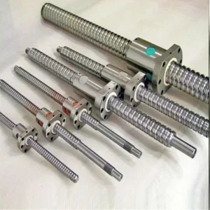
- Ball Screw and Nut Wear: This is the most common cause. Continuous use and operation under load lead to wear on the surfaces of ball screws and nuts, increasing play.
- Bearing Clearances: Clearances or wear in the bearings supporting the ball screw increase the radial and axial runout of the axis, contributing to backlash.
- Coupling Clearances: Elastic deformations or clearances in the couplings between the servo motor and the ball screw can increase the backlash effect, especially under high torque.
- Gearboxes (If Present): Some machine designs may include gearboxes between the motor and the ball screw. Clearances in these gears also become part of the backlash.
- Assembly Errors: Incorrect or loose assembly of mechanical components can also increase the backlash value.
- Thermal Expansion: Thermal expansion of metal parts due to machine heating during operation can dynamically change backlash values.
For backlash compensation to be adjusted correctly, it must first be measured precisely. Measurement methods include:
- Dial Indicator: This is the most basic and common method. A dial indicator is fixed to the machine table or spindle, and its probe is brought into contact with the surface to be axially moved (e.g., the edge of the table). The axis is moved in one direction, stopped, and then moved a very small distance (e.g., 0.1 mm) in the reverse direction. The reading on the dial indicator shows the backlash value. This process is repeated several times for each axis to obtain an average value.
- Laser Interferometer: This is the most accurate and reliable method. Laser interferometers can measure axial positioning with sub-micron precision. With this method, the difference between the actual position and the position reported by the control unit during forward and reverse movements of the axis is precisely determined. This is used to detect not only backlash but also periodic errors and other geometric errors.
- Test Part Machining: In some cases, errors occurring during the machining of complex geometry parts can indicate the presence of backlash. For example, “dog-bone” shaped protrusions at corners when machining a square pocket, or ovalities in circular interpolation, can be caused by backlash. By machining such test parts, compensation values can be optimized.
Accurately measured backlash values are entered into the relevant parameters of the CNC control unit. These parameters are usually separated by axis number (e.g., P-Backlash for X-axis, P-Backlash for Y-axis, etc.). Some modern control units have the ability to perform dynamic backlash compensation, which can adjust the compensation value depending on the machine load or speed. However, most standard systems use a single fixed value. Correct adjustment of the compensation value both increases precision and prevents unwanted effects such as vibration or noise caused by over-compensation.
| Parameter | Value/Description |
|---|---|
| Axial Backlash Tolerance | Generally 5-20 microns (0.005-0.020 mm) is acceptable. For precision machines, this value should be below 2 microns. |
| Typical Backlash Value (New Screws) | 0-5 microns (varies depending on manufacturing tolerance). Can exceed 50 microns in worn screws. |
| Measurement Methods | Dial Indicator (Digital/Analog), Laser Interferometer, Capacitive Sensors, Test Part Machining. |
| Compensation Methods | Software-based (CNC Control Unit Parameters), Mechanical (Preloaded Ball Nuts, Double Nut Systems). |
| Repeatability Impact | High backlash directly reduces axis positioning repeatability, negatively affecting part quality. |
| Surface Quality Impact | Instantaneous tool stoppage or vibration during direction changes causes marks and increased roughness on the machined surface. |
| Servo Adjustment Impact | Excessively high servo gains or incorrectly set control loop parameters can make the effect of backlash more pronounced or make compensation difficult. |
| Compensation Value Source | On-site measurements, machine manufacturer’s calibration reports, periodic maintenance records. |

Field Considerations
- Regular Measurement and Calibration: Backlash values change over time, especially with intensive machine use. Therefore, regularly measuring the backlash of each axis and updating the compensation values in the CNC control unit as part of periodic maintenance routines is critically important. Wear, bearing clearances, and other mechanical deformations continuously affect this value. Calibration must be performed during new machine installation or after a major mechanical overhaul.
- Standardization of Measurement Conditions: When performing backlash measurements, it is important that the machine has reached thermal equilibrium (is at operating temperature). Measurements taken on a cold machine may yield different results when the machine heats up. Also, ensure that no external load is applied to the axes during measurement. If a dial indicator is used, the probe must be perpendicular to the surface, and the clamping fixture must be secure, as these directly affect reading accuracy. If precision devices like laser interferometers are used, factors such as ambient temperature and air pressure affecting the measurement should also be considered.
- Prioritizing Mechanical Integrity: Backlash compensation is a software-based solution to address a mechanical problem. However, this does not mean that faulty or worn mechanical components can be completely ignored. Excessively high backlash values (e.g., above 50 microns) indicate a serious mechanical problem in the ball screw, nut, bearings, or couplings. In such cases, instead of just applying software compensation, it is essential to first inspect and, if necessary, replace or repair the mechanical components. Software compensation can mask mechanical problems and lead to larger failures in the long run.
- Vibration and Noise Control: Backlash compensation, especially at high values, can cause sudden movements during axis direction changes. These sudden movements can lead to vibration and abnormal noises in the machine. When entering the compensation value, test the machine at low speeds and gradually increase it to ensure that unwanted vibrations do not occur. Excessive compensation can cause unstable operation of the servo system and even trigger alarms.
- CNC Control Unit Parameters: Each CNC control unit (Fanuc, Siemens, Heidenhain, Mitsubishi, Fagor, etc.) has different parameter names and adjustment methods for backlash compensation. Refer to the machine’s user manual to ensure that the correct parameters are located and entered in the correct units (mm, inch, micron). Some systems may also allow entering different backlash values for positive and negative directions.
- Operator and Maintenance Team Training: Operators and maintenance technicians must have sufficient knowledge of the importance of backlash compensation, measurement methods, and parameter settings. Incorrect measurements or erroneously entered parameters can degrade machine performance and lead to costly production errors.
- Impact of Environmental Conditions: Temperature changes in the operating environment can cause thermal expansion in the machine’s mechanical components. This can dynamically affect backlash values. Especially in high-precision applications, maintaining a constant ambient temperature or using thermal compensation features can be beneficial.

Common Problems and Solutions
Many problems can be encountered during and after the backlash compensation process. Here are some common scenarios and suggested solutions:
- Problem: Dimensional Errors and Surface Quality Degradation in Machined Parts.
Solution: This usually indicates insufficient or incorrectly adjusted backlash compensation. First, re-measure the backlash value of each axis with a dial indicator or laser interferometer. Enter the measured values correctly into the relevant parameters in the CNC control unit. If the problem persists, check for excessive wear or looseness in mechanical components (ball screw, nut, bearings). Also, ensure that G-code commands for enabling/disabling compensation are used correctly during programming.
- Problem: Abnormal Noises or Vibrations During Axis Direction Changes.
Solution: This usually results from excessive backlash compensation. That is, the compensation value entered into the control unit is higher than the actual mechanical play. In this case, test the machine by gradually reducing the compensation value. Also, check the servo motor’s gain settings; excessively high gains can trigger such vibrations. Review mechanical connections (couplings, motor connections) for looseness.
- Problem: Backlash Value Increases Again in a Short Period.
Solution: This is a symptom of serious mechanical wear or damage. It means that the ball screw and nut set, bearings, or couplings may have reached the end of their service life. In this case, only software compensation will be a temporary solution. For a permanent solution, a detailed inspection, and if necessary, replacement or overhaul of the relevant mechanical components is essential. Also, ensure that the lubrication system is working properly and providing adequate lubrication.
- Problem: Discrepancies Between Values Measured with a Laser Interferometer and a Dial Indicator.
Solution: Laser interferometers perform much more precise measurements and can also detect other factors like periodic errors. The accuracy of dial indicator measurements depends on factors such as probe angle, mounting stability, and operator technique. Laser interferometer data should be preferred for a reliable result. If this is not possible, take multiple measurements from the same point and under the same conditions with a dial indicator to obtain an average value and use that value.
- Problem: Compensation Remains Ineffective in Certain Axial Movement Directions.
Solution: Some control units offer the possibility to enter different backlash values for positive and negative directions. If this feature is available, you may need to measure the backlash in both directions separately and enter them into the respective parameters. Additionally, load distribution or gravity effects on the axis can create different backlash effects in different directions. Check for mechanical friction or binding points.
Expert Advice
Backlash compensation in CNC axes is an indispensable application for achieving high precision, surface quality, and repeatability in modern manufacturing processes. This compensation mechanism eliminates errors caused by mechanical play through software, unleashing the machine’s true potential. However, the success of this process is directly related to correct measurement techniques, proper calibration, and regular maintenance. Our field experience shows that backlash compensation should not be approached merely as a software setting, but rather evaluated in conjunction with the overall health of the mechanical system. Excessively high backlash values usually indicate underlying serious mechanical problems (worn ball screws, loose bearings, or couplings), and these problems can only be temporarily masked by software compensation. For long-term efficiency and reliability, mechanical intervention should be prioritized in such situations. Furthermore, it is a critical factor for minimizing production errors and extending machine life that machine operators and maintenance teams are well-trained in the concept of backlash, measurement methods, and compensation parameters. With technological advancements, laser interferometers and other high-precision measuring devices are becoming increasingly accessible for detecting backlash and other geometric errors. Integrating these tools into periodic maintenance routines will ensure that machines continuously operate at optimal performance levels. In summary, backlash compensation is not just a parameter adjustment but an integrated maintenance and optimization process that indicates the overall health and precision of a machine. The care given to this process is one of the cornerstones of gaining a competitive advantage in the industrial automation sector.
FAQ
What is backlash in CNC axes?
Backlash in CNC axes refers to the lost motion or dead band that occurs when the direction of movement is reversed. It's the distance the drive element (like a ball screw) moves before the driven element (like the machine table) actually starts to respond. This mechanical play can lead to inaccuracies in machining.
What are the primary causes of backlash in CNC machines?
Backlash is typically caused by wear in ball screws and nuts, clearances in bearings, elastic deformation or play in couplings between the servo motor and ball screw, clearances in gearboxes (if present), assembly errors, and thermal expansion of machine components during operation.
How is backlash measured in CNC axes?
Backlash can be measured using several methods. The most common include a dial indicator for basic measurements, a laser interferometer for highly precise, sub-micron measurements, and machining test parts to observe and analyze dimensional errors or surface quality issues that indicate backlash.
How does software-based backlash compensation work?
Backlash compensation is primarily a software-based solution where the CNC control unit adds an extra movement command when the axis changes direction. This additional command virtually eliminates the mechanical play. It's configured through specific parameters in the CNC controller for each axis.
When should mechanical repairs be considered over software backlash compensation?
While software compensation is effective, it's crucial to prioritize mechanical integrity. Excessively high backlash values (e.g., over 50 microns) usually indicate significant mechanical wear or damage. In such cases, mechanical components like ball screws, nuts, or bearings should be inspected, repaired, or replaced before relying solely on software compensation.