
No products in the cart.
Using Single Flute End Mills for Aluminum Machining

Contents
- Introduction and Technical Analysis of Single Flute End Mill Use for Aluminum Machining The industrial automation sector continues its development with a continuous demand for lighter, stronger, and more efficient components. In this context, aluminum and its alloys have become an indispensable material due to their superior strength-to-weight ratio, excellent corrosion resistance, high thermal conductivity, and easy machinability. Many critical components such as robotic arms, custom fixtures for automation equipment, sensor housings, heat sinks, and machine chassis are produced from aluminum. In the production of these parts, precision, surface quality, and production speed are fundamental factors for gaining a competitive advantage. This is precisely where single flute end mills stand out as a specialized tool solution that revolutionizes aluminum machining processes. Traditionally, multi-flute end mills have been used for aluminum machining. However, aluminum’s “sticky” nature and low melting point can create challenges in chip evacuation and heat management. In multi-flute tools, chips can get jammed in narrow flutes, stick to the cutting edges (chip welding), and this can lead to undesirable results such as reduced tool life, poor surface quality on the workpiece, burring, and even tool breakage. Single flute end mills, as their name suggests, have only a single cutting edge and, consequently, an exceptionally wide chip gullet. This wide gullet ensures easy evacuation of the large volume of chips produced during the machining of soft and sticky materials like aluminum, minimizing the risk of chip clogging. This unique advantage offered by the single flute design allows the tool to operate at higher feed rates and higher spindle speeds. Higher feed rates mean that each cutting edge removes more material (higher chip load), which enables the cutting edge to “cut” more effectively rather than “rubbing” against the material. Reduced friction lowers heat generation and extends tool life. Furthermore, the lower cutting forces provided by the single flute structure offer a significant advantage, especially when machining thin-walled parts or delicate geometries, as the risk of workpiece deformation is reduced. These features make single flute end mills an ideal choice for meeting the high precision, excellent surface quality, and fast production cycle requirements demanded in the industrial automation sector. This technical article will comprehensively cover the working principles, technical details, field applications, and solutions to potential problems encountered with single flute end mills in aluminum machining. Working Principle and Technical Data of Single Flute End Mill Use for Aluminum Machining
- Tool Geometry and Material
- Cutting Parameters and Optimization
- Field Considerations for Using Single Flute End Mills for Aluminum Machining
- Common Problems and Solutions When Using Single Flute End Mills for Aluminum Machining
- Conclusion and Expert Advice on Using Single Flute End Mills for Aluminum Machining
- FAQ
Introduction and Technical Analysis of Single Flute End Mill Use for Aluminum Machining
The industrial automation sector continues its development with a continuous demand for lighter, stronger, and more efficient components. In this context, aluminum and its alloys have become an indispensable material due to their superior strength-to-weight ratio, excellent corrosion resistance, high thermal conductivity, and easy machinability. Many critical components such as robotic arms, custom fixtures for automation equipment, sensor housings, heat sinks, and machine chassis are produced from aluminum. In the production of these parts, precision, surface quality, and production speed are fundamental factors for gaining a competitive advantage. This is precisely where single flute end mills stand out as a specialized tool solution that revolutionizes aluminum machining processes.
Traditionally, multi-flute end mills have been used for aluminum machining. However, aluminum’s “sticky” nature and low melting point can create challenges in chip evacuation and heat management. In multi-flute tools, chips can get jammed in narrow flutes, stick to the cutting edges (chip welding), and this can lead to undesirable results such as reduced tool life, poor surface quality on the workpiece, burring, and even tool breakage. Single flute end mills, as their name suggests, have only a single cutting edge and, consequently, an exceptionally wide chip gullet. This wide gullet ensures easy evacuation of the large volume of chips produced during the machining of soft and sticky materials like aluminum, minimizing the risk of chip clogging.
This unique advantage offered by the single flute design allows the tool to operate at higher feed rates and higher spindle speeds. Higher feed rates mean that each cutting edge removes more material (higher chip load), which enables the cutting edge to “cut” more effectively rather than “rubbing” against the material. Reduced friction lowers heat generation and extends tool life. Furthermore, the lower cutting forces provided by the single flute structure offer a significant advantage, especially when machining thin-walled parts or delicate geometries, as the risk of workpiece deformation is reduced. These features make single flute end mills an ideal choice for meeting the high precision, excellent surface quality, and fast production cycle requirements demanded in the industrial automation sector. This technical article will comprehensively cover the working principles, technical details, field applications, and solutions to potential problems encountered with single flute end mills in aluminum machining.
Working Principle and Technical Data of Single Flute End Mill Use for Aluminum Machining
The success of single flute end mills in aluminum machining is based on the clever combination of material science and cutting geometry. These tools are designed to optimize the unique physical properties of aluminum (low density, low hardness, high ductility, and low melting point). The working principle is based on a single cutting edge, supported by a wide chip gullet, effectively removing material at high speeds and with large chip loads.
Tool Geometry and Material
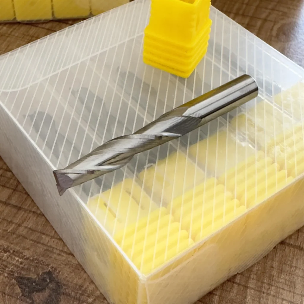
Single flute end mills are typically manufactured from high-performance solid carbide. Carbide provides long tool life in abrasive materials like aluminum due to its high hardness and wear resistance. Special coatings applied to the tool surface also enhance performance. Specifically, coatings such as TiB2 (Titanium Diboride) or ZrN (Zirconium Nitride) prevent chips from sticking to the cutting edge due to their low friction coefficients and extend tool life. These coatings also make the tool surface smoother, facilitating chip evacuation and reducing heat buildup.
In terms of geometry, single flute end mills generally have a high helix angle (45-60 degrees). A high helix angle ensures smoother application of cutting forces, which reduces vibration and helps achieve better surface quality. It also optimizes chip evacuation by allowing chips to move more efficiently upwards from the cutting zone. The cutting edge is usually very sharp and polished. Sharp edges ensure easy cutting of aluminum, while polished surfaces prevent chips from sticking to the tool, minimizing friction and heat.
Cutting Parameters and Optimization
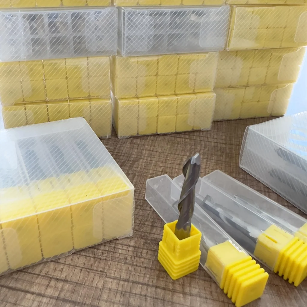
To fully utilize the potential of single flute end mills in aluminum machining, setting the correct cutting parameters is critically important.
- Spindle Speed (n): Aluminum can tolerate and even requires high cutting speeds (Vc). Single flute end mills are generally designed to operate at very high RPMs. High speeds reduce the contact time of each cutting edge with the material, which reduces heat buildup and helps achieve a smoother surface.
- Feed Rate (Vf) and Chip Load (fz): One of the key parameters for single flute end mills is to use a high chip load. Low chip loads cause the tool to “rub” on the material, leading to excessive heat generation, built-up edge, and poor surface quality. A high chip load ensures that chips are thicker and larger, which helps dissipate heat with the chip and allows the tool to cut more effectively. The feed rate, spindle speed, and chip load are interrelated by the formula (Vf = n * fz * z, where z=1 for single flute).
- Axial Depth of Cut (ap) and Radial Depth of Cut (ae): In aluminum machining, high axial depths of cut (ap) and low radial depths of cut (ae) are generally preferred. This allows the tool to utilize its entire cutting edge length while reducing radial forces, thereby minimizing vibration and tool deflection. High ap extends tool life by ensuring even wear along the cutting edge.
- Coolant/Lubrication: Effective cooling and lubrication are indispensable during aluminum machining. This prevents chips from sticking, cools the cutting zone, and extends tool life. Minimum Quantity Lubrication (MQL) or traditional flood coolant applications are used. MQL, in addition to its environmental benefits, can optimize chip evacuation and lubrication by penetrating directly and effectively into the cutting zone.
- Tool Holder and Machine Rigidity: When working with high speeds and feeds, using high-precision and rigid tool holders (e.g., shrink-fit or hydraulic holders) is essential. This minimizes tool runout, extends tool life, and improves surface quality. The machine itself must also be sufficiently rigid to absorb vibration and provide a stable machining environment.
These technical data and principles demonstrate the superior performance of single flute end mills in aluminum machining. In industrial automation applications, this enables faster production cycles, less scrap, fewer tool changes, and ultimately lower production costs. Surface quality and dimensional accuracy in precision part manufacturing can be guaranteed through these optimizations.
| Parameter | Value/Description |
|---|---|
| Tool Type | Single Flute End Mill |
| Material to be Machined | Aluminum and its Alloys (e.g., 6061, 7075) |
| Tool Material | High Performance Solid Carbide |
| Coating | TiB2 (Titanium Diboride) or ZrN (Zirconium Nitride) – Low Friction |
| Helix Angle | 45° – 60° (High Helix) |
| Cutting Speed (Vc) | 1000 – 3000 m/min (High Vc, varies by tool diameter) |
| Chip Load (fz) | 0.05 – 0.25 mm/tooth (Adjusted by tool diameter and Vc, high fz recommended) |
| Spindle Speed (n) | 10,000 – 40,000 RPM (Depending on tool diameter and Vc) |
| Feed Rate (Vf) | 500 – 5000 mm/min (Adjusted by n * fz * z formula, z=1) |
| Axial Depth of Cut (ap) | 0.5 – 2.0 * D (0.5 to 2 times tool diameter, high ap preferred) |
| Radial Depth of Cut (ae) | 0.05 – 0.2 * D (5% to 20% of tool diameter, low ae preferred) |
| Cooling/Lubrication | MQL (Minimum Quantity Lubrication) or Flood Coolant |
Field Considerations for Using Single Flute End Mills for Aluminum Machining
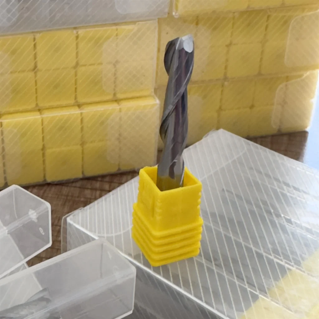
- Correct Tool Selection and Tool Material/Coating: End mills specifically designed for aluminum properties, with a single flute geometry, should be preferred. The carbide quality, helix angle, and especially low-friction coatings like TiB2 or ZrN are critically important to prevent chip sticking and extend tool life. The hardness and content of the aluminum alloy to be machined should also be considered in tool selection. For example, more wear-resistant carbides may be needed for alloys with high silicon content.
- Precise Adjustment of Cutting Parameters: Single flute end mills operate most efficiently with high spindle speeds and relatively high chip loads. Low chip loads cause the tool to rub on the material, overheat excessively, and lead to built-up edge, resulting in poor surface quality and short tool life. The manufacturer’s recommended cutting speed (Vc) and chip load (fz) values should be taken as a starting point, but fine adjustments should be made based on machine rigidity, workpiece clamping, and desired surface quality. Especially the balance between spindle speed and feed rate is vital for optimal performance.
- Effective Cooling and Chip Evacuation Management: Chip sticking and heat buildup are the biggest enemies in aluminum machining. Therefore, continuous and sufficient application of coolant (flood coolant) or Minimum Quantity Lubrication (MQL) to the cutting zone is mandatory. The pressure and flow direction of the coolant should be optimized to remove chips from the cutting zone and cool the tool. Additionally, high-pressure air blasting systems can help remove chips from the chip gullet and workpiece. Failure to properly evacuate chips can lead to tool breakage or workpiece damage.
- Machine and Tool Holder Rigidity: When working with high speeds and feeds, the rigidity of the machine and tool holder system directly affects tool life and surface quality. High-precision, low-runout tool holders (e.g., shrink-fit or hydraulic holders) should be used, and the tool should be held as short as possible. Any runout or vibration can cause premature tool wear, breakage, and poor surface quality. The machine itself must also have sufficient power, high-speed machining capability, and vibration damping properties.
- Workpiece Clamping and Vibration Control: Secure and vibration-free clamping of the workpiece is fundamental for a successful machining process. Weak clamping can cause chatter during machining, leading to tool breakage, poor surface quality, and dimensional deviations. Especially when machining thin-walled or complex geometry aluminum parts, special fixtures and support points should be used to prevent workpiece deformation. Vibration sensors or acoustic monitoring systems can help detect potential problems early.
- Tool Life Monitoring and Wear Management: Regardless of how durable single flute end mills are, regular tool wear monitoring should be performed. Indications such as micro-chipping on the cutting edge, excessive wear, or loss of coating are signs that the tool needs to be replaced. Continuing to work with a worn tool reduces workpiece quality, increases the risk of tool breakage, and can lead to higher costs. To optimize tool life, sensors that monitor tool wear or periodic visual inspections should be implemented.
- Surface Quality and Dimensional Accuracy Control: The surface quality and dimensional accuracy of manufactured parts are critically important in the industrial automation sector. Periodic post-machining inspections should check for surface roughness, burring, and dimensional deviations. Feedback from these inspections should be used to optimize cutting parameters and tool selection. If necessary, different parameters such as lower chip loads and higher speeds can be tried for secondary finishing operations.
Common Problems and Solutions When Using Single Flute End Mills for Aluminum Machining
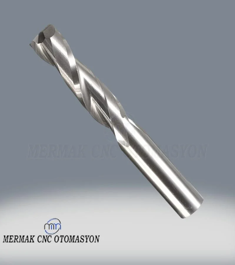
While single flute end mills offer many advantages in aluminum machining, some common problems can be encountered due to incorrect application or unoptimized parameters. Understanding these problems and implementing effective solutions is vital to maintaining production efficiency and product quality.
- Chip Welding / Built-Up Edge:
Problem: Aluminum chips sticking to the cutting edge or machined surface, which reduces tool cutting performance, degrades surface quality, and shortens tool life. This usually results from insufficient chip evacuation, excessive heat buildup, or low chip loads.
Solution:- Increase Chip Load: Increase the chip load to ensure the tool “cuts” rather than “rubs” the material. This reduces heat generation and makes chips larger and easier to evacuate.
- Apply Effective Cooling: Dissipate heat and prevent chips from sticking by applying plenty of flood coolant or MQL (Minimum Quantity Lubrication) to the cutting zone. The pressure and flow direction of the coolant should be adjusted to clear chips from the area.
- Use Coated Tools: Tools with low-friction coatings like TiB2 or ZrN significantly reduce chip sticking to the cutting edge.
- High Helix Angle Tools: A high helix angle helps chips evacuate upwards more quickly and efficiently.
- Poor Surface Finish / Burring:
Problem: Roughness, scratches, or undesirable burr formation on the machined surface. This is typically caused by insufficient tool sharpness, incorrect cutting parameters, or vibration.
Solution:- Optimal Chip Load and Spindle Speed: A chip load that is too low causes the tool to rub, reducing surface quality. Maintain optimal chip load by keeping spindle speed and feed within the manufacturer’s recommended ranges.
- Use Sharp Tools: Worn or dull tools lead to poor surface quality. Regularly inspect the tool and replace it when it shows signs of wear.
- Reduce Vibration: Increase machine rigidity, check the tool holder (low runout), securely clamp the workpiece, and adjust cutting depth/width to reduce vibration.
- Cooling and Chip Evacuation: Insufficient cooling and chip evacuation can also cause burring. Ensure the cutting zone is clean and cool.
- Tool Breakage:
Problem: Sudden tool breakage during machining. This is usually caused by excessive load, vibration, chip clogging, or tool wear.
Solution:- Check Cutting Parameters: Excessively high chip load or depth of cut can cause excessive stress on the tool. Find the optimum point by gradually increasing parameters.
- Eliminate Vibration: Vibration can lead to tool fatigue and breakage. Check the rigidity of the machine, tool holder, and workpiece clamping.
- Improve Chip Evacuation: Chip clogging can cause sudden loading of the tool. Ensure chips are effectively evacuated with coolant and air blasting.
- Monitor Tool Wear: An excessively worn tool weakens and becomes more prone to breakage. Regularly inspect the tool and replace it in a timely manner.
- Tool Path Optimization: Use smooth tool paths instead of sudden direction changes or variations in cutting depth.
- Chatter:
Problem: High-pitched noise, machine shaking, and wavy marks (chatter marks) on the machined surface during machining.
Solution:- Adjust Cutting Depth and Width: Try to reduce vibration by changing ap and ae values. Generally, a combination of lower ae and higher ap can reduce vibration.
- Change Spindle Speed: Increase or decrease spindle speed to avoid resonance frequencies.
- Increase Rigidity: Use a more rigid tool holder, shorten tool overhang, and clamp the workpiece more securely.
- Tool Geometry: Tools with different helix angles or variable helix angles can help reduce vibration.
- Short Tool Life:
Problem: Tool wears out or dulls faster than expected.
Solution:- Parameter Optimization: Excessively high or low chip loads, or incorrect cutting speeds, can shorten tool life. Optimize parameters using manufacturer recommendations as a starting point.
- Effective Cooling: Insufficient cooling causes the tool to overheat and wear out quickly.
- Correct Tool Selection: Ensure you select the most suitable tool with the appropriate coating and geometry for the material and application.
- Vibration Control: Vibration causes excessive mechanical loads on the tool, shortening its life.
- Tool Holder Quality: High runout leads to uneven tool wear. Use high-precision tool holders.
Conclusion and Expert Advice on Using Single Flute End Mills for Aluminum Machining
In the dynamic and demanding environment of the industrial automation sector, machining critical materials like aluminum brings with it a continuous quest for higher efficiency, precision, and cost-effectiveness. Single flute end mills represent a turning point in this quest, offering a modern and superior solution to the traditional challenges encountered in aluminum machining. With their wide chip gullet, sharp cutting edge, high helix angle, and special coating options, these tools turn aluminum’s “sticky” nature into an advantage, maximizing chip evacuation, minimizing heat generation, and ultimately dramatically improving machined surface quality and tool life.
Our field experience clearly shows that when single flute end mills are used with the correct parameters and appropriate system rigidity, they can achieve significantly higher material removal rates (MRR) compared to their multi-flute counterparts, while also providing excellent surface finishes with less burring. This reduces the need for additional secondary operations, especially in the production of critical automation parts such as lightweight components for robotic arms, precise sensor housings, or heat sinks, thereby lowering the overall production time and cost. However, to fully unlock this potential, it is necessary not only to select the right tool but also to optimize machine dynamics, workpiece clamping techniques, cooling strategies, and cutting parameters with a holistic approach. High spindle speeds, high chip loads, and effective chip evacuation are key elements of this equation.
As expert advice, businesses should adopt a trial-and-error approach when implementing single flute end mills, starting with manufacturer recommendations and gradually fine-tuning parameters based on specific application requirements and machine capabilities. Investing in high-quality tool holders and ensuring machine rigidity are also crucial for long-term success. For tailored solutions and to request a quote on the best single flute end mills for your aluminum machining needs, please contact Mermak CNC on WhatsApp. Our experts are ready to assist you in optimizing your production processes and achieving superior results.
FAQ
Why are single flute end mills particularly effective for machining aluminum?
Single flute end mills are ideal for aluminum due to their large chip gullet, which allows for efficient chip evacuation, preventing chip welding and heat buildup. Their sharp cutting edge and high helix angle also contribute to a superior surface finish and extended tool life, even at high feed rates and spindle speeds.
What are the optimal cutting parameters for using single flute end mills on aluminum?
Key parameters include high spindle speeds (RPM), high chip loads (fz), and effective cooling/lubrication. High axial depths of cut (ap) combined with low radial depths of cut (ae) are also recommended to maximize material removal while maintaining surface quality and reducing vibration.
What are the common problems encountered when machining aluminum with single flute end mills, and how can they be resolved?
Common issues include chip welding, poor surface finish, tool breakage, and chatter. Solutions involve optimizing chip load, ensuring effective cooling, using coated tools, verifying machine and tool holder rigidity, and monitoring tool wear. Adjusting spindle speed and feed rate can also mitigate chatter.
What features should I look for when selecting a single flute end mill for aluminum?
Look for high-performance solid carbide tools with low-friction coatings like TiB2 or ZrN. A high helix angle (45-60 degrees) and a polished, sharp cutting edge are also crucial for optimal performance and chip evacuation in aluminum.
Is tool holder rigidity important when using single flute end mills for aluminum?
Yes, high-precision and rigid tool holders (e.g., shrink-fit or hydraulic) are essential to minimize runout and vibration, especially when operating at high speeds and feeds. This directly impacts tool life and the quality of the machined surface.



