
No products in the cart.
Wiring Diagram for Servo Motors with Electromagnetic Brakes: A Field Guide
Contents
- Introduction and Technical Analysis of Electromagnetic Brake Servo Motor Wiring Diagrams
- Operating Principle and Technical Data of Electromagnetic Brake Servo Motor Wiring Diagrams
- Field Considerations for Electromagnetic Brake Servo Motor Wiring Diagrams
- Common Problems and Solutions for Electromagnetic Brake Servo Motor Wiring Diagrams
- Conclusion and Expert Advice on Electromagnetic Brake Servo Motor Wiring Diagrams
- FAQ
body { font-family: ‘Segoe UI’, Tahoma, Geneva, Verdana, sans-serif; line-height: 1.6; color: #333; margin: 20px; background-color: #f4f4f4; }
h1, h2, h3, h4, h5 { color: #2c3e50; margin-top: 30px; margin-bottom: 15px; }
h2 { border-bottom: 2px solid #3498db; padding-bottom: 10px; }
h3 { border-bottom: 1px solid #3498db; padding-bottom: 5px; }
p { margin-bottom: 15px; text-align: justify; }
ul { list-style-type: disc; margin-left: 20px; margin-bottom: 15px; }
li { margin-bottom: 8px; }
strong { color: #e74c3c; }
table { border-collapse: collapse; width: 100%; margin: 20px 0; background-color: #fff; box-shadow: 0 0 10px rgba(0,0,0,0.1); }
th, td { border: 1px solid #ddd; padding: 12px; text-align: left; }
th { background-color: #3498db; color: white; }
tbody tr:nth-child(even) { background-color: #f2f2f2; }
a { color: #3498db; text-decoration: none; }
a:hover { text-decoration: underline; }
Introduction and Technical Analysis of Electromagnetic Brake Servo Motor Wiring Diagrams
The world of industrial automation places critical importance on precision, speed, and reliability. In this context, servo motors have become indispensable components across a wide range of applications, from production lines to robotic systems, CNC machines, and lifting equipment. However, especially in vertical axis applications, when controlling high-inertia loads, or when a load needs to maintain its position safely during a power outage, standard servo motors may prove insufficient. This is where servo motors with electromagnetic brakes come into play. These motors, with an integrated braking mechanism, securely hold the load when the motor stops or power is cut, thereby enhancing both operational safety and overall system performance. A correct wiring diagram forms the foundation for the smooth, efficient, and safe operation of this complex system. This article serves as a comprehensive guide for experts and technicians in the industrial automation sector, covering wiring diagrams, operating principles, critical field considerations, and troubleshooting solutions for servo motors with electromagnetic brakes.
Proper integration of an electromagnetic brake servo motor involves more than just the physical connections of the motor and brake. This process requires a complete understanding of the electrical and logical communication between the servo drive, encoder (feedback unit), power supply, controller (PLC/HMI), and other peripheral components. Incorrect wiring can lead to system failures, unexpected movements, equipment damage, or, worse, serious industrial accidents. Therefore, grasping the role and connection point of each component in detail is vital for project success. This technical analysis aims to simplify the complexity of these systems and provide practical, actionable information to field engineers. In the continuously evolving dynamics of industrial automation, the correct integration of such specialized components is a critical factor for competitive advantage and operational excellence.
Operating Principle and Technical Data of Electromagnetic Brake Servo Motor Wiring Diagrams
Electromagnetic brake servo motors fundamentally consist of a servo motor and an integrated electromagnetic brake unit. A servo motor is an electric motor precisely controlled by a servo drive, operating with position, speed, and torque feedback. This feedback is typically provided by an encoder. The encoder continuously measures the angular position and speed of the motor shaft, reporting this information to the drive, which then compares it with reference values to make instantaneous adjustments to the motor. This closed-loop control mechanism ensures high precision and dynamic response.
The electromagnetic brake typically operates on a “fail-safe” principle, meaning it engages when power is cut. In these types of brakes, when no power is supplied to the coil, springs or magnets compress the brake pads, locking the motor shaft. When DC voltage (usually 24V DC) is applied to the brake coil, an electromagnetic field is generated. This field overcomes the spring force, releasing the pads and allowing the motor shaft to rotate. The brake’s engagement and disengagement are usually controlled via the digital outputs of the servo drive. The drive releases the brake when the motor needs to move and engages it when the motor stops or during a power outage. This is critically important, especially in vertical axes, to prevent the load from slipping down or to instantly secure the load during emergency stops.
Wiring Diagram Details:
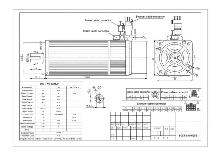
- Motor Power Connection: The three-phase power cables (U, V, W) and the ground (PE) line of the servo motor are typically connected to the motor output terminals of the servo drive via specialized shielded and flexible cables. It is crucial that the cross-section of these cables matches the motor’s nominal current and that the shielding is properly connected to the drive’s chassis to prevent electromagnetic interference (EMI/RFI).
- Encoder Connection: The encoder cable transmits position and speed information of the motor shaft to the servo drive. This cable usually contains differential signals (A/A-, B/B-, Z/Z-) and the encoder’s supply voltage lines (typically 5V or 12V DC). Due to the sensitive nature of these signals, it is highly recommended that the encoder cable also be shielded and routed separately from power cables. Error-free pin connections, according to manufacturer documentation, prevent issues such as position errors and vibrations.
- Brake Power and Control Connection: A separate DC power supply (typically 24V DC) is required for the brake coil. The output of this power supply is connected to the brake coil, usually via a relay or an internal transistor switch controlled by a digital output of the servo drive. When the motor needs to operate, the drive activates this digital output, energizing the brake coil and releasing the brake. When the motor stops or during an emergency stop, the drive deactivates the output, and the brake engages. Some advanced drives may have dedicated terminals for brake control.
- Control and Communication Connections: The servo drive typically communicates with a PLC (Programmable Logic Controller) or another main controller. This communication is carried out via industrial communication protocols such as EtherCAT, PROFINET, Modbus TCP/RTU, or CANopen. Additionally, the drive has digital inputs (e.g., limit switches, emergency stop) and digital outputs (e.g., error signals, brake status). These connections are necessary for integrating the system into the overall automation logic.
| Parameter | Value/Description |
|---|---|
| Brake Type | Electromagnetic, Fail-Safe (Power-Off Brake) |
| Brake Supply Voltage | Typically 24V DC (±10% Tolerance) |
| Brake Operating Current | 0.3A – 1.5A (Varies by motor size and brake) |
| Brake Torque | 0.5 Nm – 50 Nm (50-100% of motor nominal torque) |
| Brake Release Time | 20 ms – 150 ms (Typical) |
| Brake Engagement Time | 10 ms – 100 ms (Typical) |
| Encoder Type | Incremental or Absolute |
| Motor Power Range | 50W – 15kW (Application-specific variability) |
Field Considerations for Electromagnetic Brake Servo Motor Wiring Diagrams
- Cable Selection and Routing: Motor power cables, encoder cables, and brake control cables have different electrical characteristics and must be selected and routed appropriately. Power cables (high current and noise) should be shielded and run in separate conduits or at a sufficient distance from signal cables (low current, sensitive data). Flexible (drag chain-rated) cables extend cable life in moving applications. Proper connection of the shielding to the drive and motor chassis minimizes EMI/RFI interference.
- Grounding Principles: Proper single-point grounding of the entire system is essential for reducing electrical noise and ensuring safety. Grounding connections between the servo drive, motor housing, control panel, and external chassis must be low-impedance and robust. Incorrect grounding can lead to encoder signal errors, unexpected faults, and safety risks. Manufacturer’s grounding diagrams must be strictly followed.
- Connector and Terminal Connections: All connectors (power, encoder, brake) and terminal connections must be made securely and with the correct pin assignment according to manufacturer instructions. Loose connections can lead to arcing, signal loss, and even fire over time. Ensure that the IP (Ingress Protection) rating of connectors used in industrial environments is suitable for environmental conditions (dust, moisture, vibration). Using ferrules on cable ends and applying appropriate tightening torques increases connection reliability.
- Brake Control Logic and Safety: The timing of brake release and engagement must be carefully programmed according to application requirements. For example, in vertical axes, the brake should not engage before the motor stops, but it must securely hold the load immediately after the motor stops. In emergency stop (E-STOP) situations, integration with appropriate safety relays or safety PLCs should be considered to ensure instantaneous brake engagement. Brake control is usually done via the drive, but in some critical applications, direct control with an external safety circuit may be preferred. Care should be taken to prevent the brake from remaining continuously energized to avoid overheating.
- Insulation and Testing: After completing the connections, especially in power circuits, performing insulation tests (megger test) between cables and between cables and ground is important to detect short circuits or insulation faults. These tests eliminate potential hazards before initial system power-up and extend equipment life. Additionally, visually inspecting and labeling all cable connections facilitates future maintenance and troubleshooting processes.
- Manufacturer Documentation and Standards: Every servo motor and drive manufacturer provides specific wiring diagrams and installation instructions. Thorough and meticulous review of these documents is the most reliable way to prevent potential errors. Furthermore, adhering to local and international industrial standards (e.g., IEC, UL) ensures system safety and legal compliance.
Common Problems and Solutions for Electromagnetic Brake Servo Motor Wiring Diagrams
Problems encountered in electromagnetic brake servo motor systems typically arise from electrical connection errors, incorrect parameter settings, or mechanical faults. The ability of field technicians to quickly and effectively resolve these issues is critical for production continuity.
-
Problem: Brake Not Releasing or Engaging (Motor Not Turning / Not Holding Load)
- Possible Causes:
- No or incorrect brake coil supply voltage.
- Brake control signal (from drive) is missing or incorrectly configured.
- Brake cable broken, short-circuited, or incorrectly wired.
- Brake coil faulty (open circuit or short circuit).
- Brake mechanically jammed or pads worn out.
- Solutions:
- Check the brake’s DC supply voltage (usually 24V DC) with a multimeter. Ensure the power supply is operational.
- Check if the servo drive’s brake control output is active (monitor PLC program and drive digital output status).
- Test the continuity of brake cables and verify correct pin connections.
- Measure the resistance of the brake coil (compare with manufacturer data). If values differ significantly, the coil may be faulty.
- Manually check the motor brake (by cutting and applying power) and observe its mechanical movement. Clean or replace the brake if necessary.
- Possible Causes:
-
Problem: Motor Vibration, Position Error, or Excessive Noise
- Possible Causes:
- Encoder connection faulty, loose, or noisy.
- Encoder faulty.
- Motor power cables incorrectly wired (phase sequence), loose, or insufficiently shielded.
- Incorrect servo drive PID gain settings.
- Backlash or resonance in the mechanical load.
- Solutions:
- Check all pin connections of the encoder cable, ensuring no looseness. Verify proper shielding.
- Check encoder signals (A, B, Z) with an oscilloscope to ensure they are clean and correctly formed.
- Check the phase sequence and connections of the motor power cables. Ensure proper grounding.
- Optimize PID gains using the servo drive’s auto-tuning feature or manually.
- Check and eliminate backlash or vibration sources in the mechanical system.
- Possible Causes:
-
Problem: Overheating (Motor or Brake)
- Possible Causes:
- Motor operating under excessive load.
- Brake remaining continuously energized or frequent engagement/disengagement (high cycle count).
- Incorrect brake torque selection (struggling to hold the load).
- High ambient temperature or insufficient cooling.
- Brake partially engaged (friction).
- Solutions:
- Review the motor’s duty cycle and load profile; if necessary, increase motor power or optimize operating conditions.
- Check the brake’s control logic, ensuring it is not unnecessarily or continuously energized. Reduce brake engagement/disengagement cycles.
- Ensure the brake torque is suitable for the application. Use a higher torque brake if necessary.
- Check cooling systems to reduce ambient temperature or improve airflow around the motor/brake.
- Perform a mechanical inspection to ensure the brake fully releases and engages.
- Possible Causes:
-
Problem: EMI/RFI Interference and Loss of Control
- Possible Causes:
- Insufficient cable shielding or incorrect grounding.
- Power and signal cables routed too close to each other.
- Ground loops.
- Weak chassis grounding of the drive or motor.
- Çözümler:
- Ensure all cables (especially motor power and encoder) are properly shielded and that the shielding is connected to the drive and motor chassis with low impedance.
- Route power cables in separate conduits or maintain sufficient distance from signal cables.
- Implement single-point grounding principles.
- Add ferrite filters to cables if necessary.
- Check that all grounding connections are solid and free from corrosion.
- Possible Causes:
Conclusion and Expert Advice on Electromagnetic Brake Servo Motor Wiring Diagrams
The wiring diagram for servo motors with electromagnetic brakes is a critical element at the heart of industrial automation systems, directly impacting performance, safety, and operational efficiency. As emphasized throughout this detailed field guide and technical article, successful integration of such systems requires much more than simply connecting cables to the correct terminals. Every step, from the motor’s power connections to the encoder’s precise signal transmission, from the safe control of the brake to the system’s overall grounding strategy, must be handled with meticulousness, knowledge, and experience. An incorrect or incomplete connection can lead to more than just a simple fault; it can result in production downtime, costly equipment damage, and most importantly, serious occupational safety risks.
As an expert working in industrial automation, my advice is to always refer to the manufacturer’s documentation, specifically the user manuals and wiring diagrams for the motor and drive, as your primary reference. These documents contain device-specific details and critical warnings. Furthermore, adhering to national and international standards (e.g., NEMA, IEC, UL) during cabling and installation processes ensures the system’s longevity and safety. Special attention should be given to the brake control logic and emergency stop scenarios, particularly in vertical axis applications and systems controlling high-inertia loads. The correct integration of safety relays, safety PLCs, and other safety functions plays a vital role in preventing potential accidents. Our field experience shows that proper planning, selection of quality materials, and meticulous installation at the outset eliminate a significant portion of problems that may arise later. Periodic maintenance, checking connections, and software updates are also indispensable for maintaining optimal system performance. It should be remembered that success in industrial automation is directly proportional to attention to detail and continuous learning. This knowledge not only helps resolve faults but also paves the way for developing more efficient, safer, and innovative automation solutions.

FAQ
What is an electromagnetic brake servo motor and how does it differ from a standard servo motor?
An electromagnetic brake servo motor combines a standard servo motor with an integrated fail-safe electromagnetic brake. This brake automatically engages when power is removed or when the motor stops, securely holding the load in place. This is crucial for vertical axis applications and high-inertia loads to prevent unexpected movement and enhance safety.
What are the main components of an electromagnetic brake servo motor system?
Key components include the servo motor itself, the electromagnetic brake unit, a servo drive, an encoder for feedback, a DC power supply for the brake, and a main controller (like a PLC or HMI) for overall system management and communication.
How is the electromagnetic brake controlled and powered within the servo system?
The brake coil typically requires a separate DC power supply, usually 24V DC. The servo drive's digital output often controls a relay or internal switch that energizes the brake coil to release the brake and de-energizes it to engage the brake. This ensures the brake is engaged when the motor is stopped or power is lost.
What are the critical considerations for wiring and installing these motors in industrial environments?
Proper cable selection (shielded, flexible), correct routing (separating power and signal cables), robust single-point grounding, secure connector and terminal connections, and careful programming of the brake control logic are essential. Always refer to the manufacturer's documentation and adhere to industrial standards (e.g., IEC, UL).
What are some common problems encountered with electromagnetic brake servo motor wiring and how can they be resolved?
Common issues include the brake not releasing/engaging (check power, control signal, coil, mechanical state), motor vibration/position errors (check encoder, power cables, PID tuning, mechanical backlash), overheating (check load, brake cycle, cooling), and EMI/RFI interference (check shielding, grounding, cable routing). Troubleshooting often involves multimeter checks, oscilloscope signal verification, and system parameter optimization.



