
No products in the cart.
What is a CNC Tool Setter Sensor (Z-Probe) and How to Use It?
Contents
- What is a CNC Tool Setter Sensor (Z-Probe) and How to Use It? Introduction and Technical Analysis In the world of industrial automation and precision manufacturing, the efficiency and machining quality of CNC (Computer Numerical Control) machines are directly dependent on the accurate zeroing of the tool relative to the machine’s coordinate system. In this critical process, the time loss, human error risk, and inconsistencies introduced by manual methods have become unacceptable in modern production environments. This is where the CNC Tool Setter Sensor, or more commonly known as the Z-Probe (Z-Axis Probe), offers a revolutionary solution to manufacturing processes. A Z-Probe is an electronic device used to automatically and precisely determine the Z-axis position of the tool on the workpiece or machine table. These sensors standardize tool length measurement, significantly reducing machine setup time, increasing machining accuracy, and minimizing operator intervention. Especially in high-volume production, complex part machining, and applications where multiple tool changes are frequent, the advantages provided by a Z-Probe are indispensable. This technical article and field guide will comprehensively cover what a Z-Probe is, how it works, its correct usage, and potential issues that industrial automation professionals may encounter. What is a CNC Tool Setter Sensor (Z-Probe) and How to Use It? Working Principle and Technical Data
- Working Principle Details:
- Application Areas:
- Engineering Data and Selection Criteria:
- What is a CNC Tool Setter Sensor (Z-Probe) and How to Use It? Field Considerations
- What is a CNC Tool Setter Sensor (Z-Probe) and How to Use It? Common Problems and Solutions
- What is a CNC Tool Setter Sensor (Z-Probe) and How to Use It? Conclusion and Expert Advice
- FAQ
What is a CNC Tool Setter Sensor (Z-Probe) and How to Use It? Introduction and Technical Analysis
In the world of industrial automation and precision manufacturing, the efficiency and machining quality of CNC (Computer Numerical Control) machines are directly dependent on the accurate zeroing of the tool relative to the machine’s coordinate system. In this critical process, the time loss, human error risk, and inconsistencies introduced by manual methods have become unacceptable in modern production environments. This is where the CNC Tool Setter Sensor, or more commonly known as the Z-Probe (Z-Axis Probe), offers a revolutionary solution to manufacturing processes. A Z-Probe is an electronic device used to automatically and precisely determine the Z-axis position of the tool on the workpiece or machine table. These sensors standardize tool length measurement, significantly reducing machine setup time, increasing machining accuracy, and minimizing operator intervention. Especially in high-volume production, complex part machining, and applications where multiple tool changes are frequent, the advantages provided by a Z-Probe are indispensable. This technical article and field guide will comprehensively cover what a Z-Probe is, how it works, its correct usage, and potential issues that industrial automation professionals may encounter.
What is a CNC Tool Setter Sensor (Z-Probe) and How to Use It? Working Principle and Technical Data
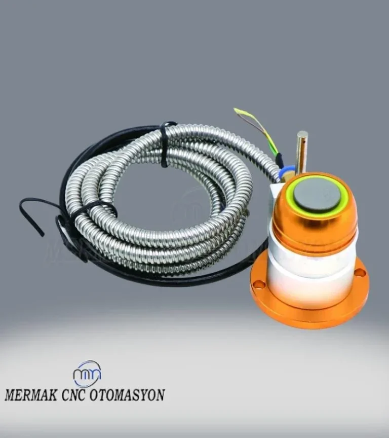
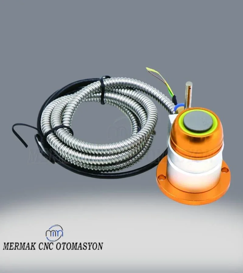
CNC Tool Setter Sensors (Z-Probes) typically consist of a contact surface and a switch mechanism that generates an electrical signal when this surface is touched. The basic working principle is quite simple: the CNC tool tip is moved towards the sensor’s contact surface at a controlled speed. As soon as the tool tip touches the sensor, the sensor generates a signal (usually an NC – Normally Closed or NO – Normally Open contact change), and this signal is transmitted to the CNC control unit. When the control unit receives this signal, it records the tool’s current Z-axis position and processes this value as the tool length offset. This process can be automatically repeated after each tool change, thus precisely determining the correct Z-zero point for each tool.
Working Principle Details:
- Mechanical Contact Principle: This is the most common type of Z-Probe. The top part of the sensor is usually a conductive metal plate or a button. When the tool tip touches this plate, an internal microswitch is triggered, closing or opening the electrical circuit. This signal informs the CNC controller that it has been “triggered.”
- Conductivity Principle: Some Z-Probes require the tool itself to be conductive. The sensor’s contact surface is part of an electrical circuit. When the tool tip (if conductive) touches the sensor, it completes the circuit and generates a signal. These types of sensors are preferred especially in metal machining applications.
- Accuracy and Repeatability: The most critical features of Z-Probes are their measurement accuracy and repeatability. Industrial-grade sensors typically offer repeatability at the micron level (±1 to ±5 microns). This indicates how close the values obtained are when the same tool is measured multiple times. High repeatability is vital for maintaining machining quality and part tolerances.
Application Areas:
Z-Probes are used in a wide range of CNC machines:
- CNC Milling Machines and Machining Centers: This is the most common application area. Automatic measurement of tool length and updating of offsets with each tool change.
- CNC Routers: Used in routers that process materials such as wood, plastic, and composites to zero the tool relative to the material surface.
- CNC Engraving Machines: Ensures the tool operates at the correct depth in precise engraving operations.
- Lathes (with Special Tool Setters): While tool setters working on a similar principle are also found in lathes, the term Z-Probe is generally used for milling-type machines.

Engineering Data and Selection Criteria:
Engineering data and features to consider when selecting a Z-Probe include:
- Trigger Force: The minimum force required to trigger the sensor. Very low forces can increase sensitivity but may lead to false triggers. Very high forces can damage the tool tip.
- Protection Class (IP Rating): Indicates the sensor’s resistance to dust and liquid ingress (e.g., IP67: Completely dust-tight, resistant to water up to 1 meter for 30 minutes). A high IP rating is important in environments where aggressive coolants are used.
- Housing Material: Durable materials such as stainless steel and anodized aluminum are preferred.
- Connection Type: Wired (usually 2 or 3-wire) or wireless (RF, infrared) options are available. Wireless sensors eliminate cable clutter, but factors such as battery life and signal reliability must be considered.
- Output Signal Type: Different electronic interfaces such as NPN, PNP, or voltage output. Must be compatible with the CNC control unit’s input type.
- Signal Delay: The time between the sensor being triggered and the signal reaching the controller. The shorter this time, the more accurate the measurement.
| Parameter | Value/Description |
|---|---|
| Measurement Principle | Mechanical Contact (Microswitch) or Conductivity-Based |
| Repeatability | ±1 micron (0.001 mm) to ±5 microns (0.005 mm) |
| Trigger Force | 0.5N to 1.5N (Typically adjustable or fixed) |
| Protection Class | IP67 (High protection against dust and water) |
| Housing Material | Anodized Aluminum, Stainless Steel |
| Connection Type | Wired (2 or 3-Wire), Wireless (RF, IR) |
| Output Signal | NPN/PNP (Typically NC – Normally Closed) |
| Operating Voltage | DC 5V – 24V |
What is a CNC Tool Setter Sensor (Z-Probe) and How to Use It? Field Considerations
- Correct Mounting and Calibration: The performance of a Z-Probe begins with correct mounting. The sensor should be securely fastened to a vibration-free, solid surface, machine table, or a special mounting fixture. During mounting, ensure that the sensor’s surface is parallel to the machine table or the reference surface of the workpiece to be machined. Before initial use, the known height of the sensor (its absolute position in the Z-axis) must be precisely calibrated. This calibration is typically done with a master block or a precision caliper and entered into the control unit as an offset value. Periodically checking this calibration is critical for long-term accuracy.
- Cleaning and Maintenance: The contact surface and general structure of the Z-Probe must be free from chips, coolant residues, dust, and other contaminants. A dirty surface can lead to false or inconsistent triggers, causing measurement errors. Aggressive coolants and metal chips, in particular, can damage the mechanical or electrical components of the sensor. Regular cleaning with compressed air and wiping with an alcohol-soaked cloth if necessary is recommended. Visual inspections should be performed for signs of wear or damage on the sensor’s moving parts (if any).
- Tool Material and Tip Compatibility: Most Z-Probes expect the tool to be conductive. Metal tools such as carbide and HSS work without issues, while special solutions or different probe types may be required for the tips of ceramic or diamond-coated (non-conductive) tools. The shape of the tool tip is also important; very sharp or very small diameter tools can damage the probe surface or fail to establish a stable contact point. The contact speed should be reduced, especially for small tools.
- Software Integration and G-Code: The effective use of a Z-Probe is directly related to the CNC control unit’s software and the G-code programming used. Typically, a tool setting cycle (probing cycle) is initiated with a special G-code (e.g., G31 in Fanuc, G31.1 in Mach3) or a macro program. This program determines the speed at which the tool moves towards the sensor, safety distances, and how to record the tool length offset after triggering. Operators and programmers must thoroughly understand and correctly implement these G-code cycles and tool offset management commands (G43, G43.1, etc.).
- Environmental Conditions and Protection from Electrical Noise: CNC machines typically operate in noisy (electrical and mechanical) environments. Electromagnetic interference (EMI) from devices such as electric motors, contactors, and power supplies can affect the Z-Probe’s signal cables, leading to false triggers or signal loss. Using high-quality shielded cables, routing cables separately from power cables, and ensuring proper grounding of the sensor minimizes such problems. Extreme temperature changes or high humidity can also affect sensor performance; therefore, the sensor’s operating temperature and humidity ranges should be considered.
What is a CNC Tool Setter Sensor (Z-Probe) and How to Use It? Common Problems and Solutions
Z-Probes provide great convenience in CNC operations, but various problems can sometimes be encountered. Most of these problems can be resolved with simple checks and correct interventions.
- False Triggering or No Triggering:
- Problem: The tool gives a signal before touching the probe or does not give a signal when it touches.
- Solution:
- Clean the sensor’s contact surface and the tool tip. Dirt, oil, or chip buildup can cause false contact.
- Check the cables. Loose connections, cut, or damaged cables can prevent signal transmission.
- Examine sources of electrical noise. EMI from other components in the machine can lead to false triggers. Use shielded cables and check grounding.
- Ensure that the internal switch mechanism of the sensor is not physically jammed or worn. Replace the sensor if necessary.
- Ensure that the input signal settings (NPN/PNP, NO/NC) in the control unit match the sensor’s output type.
- Inconsistent or Incorrect Measurements:
- Problem: The same tool gives different Z values when measured multiple times, or the measured values are outside expectations.
- Solution:
- Ensure that the sensor’s mounting is secure, free from vibration, and parallel to the machine table.
- Check for runout in the tool holder and the tool itself. High runout can change the contact point.
- Check the feed rate in the tool setting cycle (G-code). Very high speeds can cause a delay in the control unit’s signal detection. Use a slow “approach” speed and an even slower “probe” speed, especially for precise measurements.
- Recheck the sensor’s calibration value (known height) and recalibrate if necessary.
- Check for backlash issues in the machine axes. Backlash can prevent accurate Z-axis positioning.
- Environmental temperature changes can also affect accuracy. If possible, measure in a stable environment.
- Communication Problems with the CNC Controller:
- Problem: The sensor sends a signal, but the control unit does not detect it, or the probe cycle does not start.
- Solution:
- Check that the sensor is connected to the correct input pin on the control unit and that this pin is correctly configured in the software.
- Verify the control unit’s input signal by comparing it directly with the signal from the sensor using a multimeter.
- Ensure that the G-code program or macro is correct and that the control unit supports these commands.
- In the control unit’s settings (e.g., “Ports and Pins” settings in Mach3), ensure that the relevant probe input is enabled.
- Tool Crash:
- Problem: The tool approaches the probe too quickly, overshoots the probe, or crashes into the probe when it is not active.
- Solution:
- Check the safety distances (rapid traverse height, approach height) and feed rates in the G-code program and set them to safe values.
- Ensure that the probe is active (usually indicated by a light or LED) before starting the probe cycle.
- Ensure that the emergency stop (E-stop) button is always accessible and intervene immediately in case of a potential crash.
- Ensure that the operator visually checks the tool’s position before starting the probe cycle.
What is a CNC Tool Setter Sensor (Z-Probe) and How to Use It? Conclusion and Expert Advice
CNC tool setter sensors are an indispensable component of modern manufacturing facilities. By eliminating the countless difficulties and errors caused by manual tool measurement in the past, they have become one of the cornerstones of industrial automation. Investing in a Z-Probe not only saves time but also increases machining accuracy, reduces scrap rates, extends tool life, and most importantly, enhances operator safety. Based on our field experience, correct integration and regular maintenance of these sensors are vital for long-term and trouble-free operation. Selecting a high-quality Z-Probe, appropriate mounting techniques, seamless integration with CNC control software, and adequate training for operators to effectively use these systems are key to successful implementation. While many models are available in the market for different budgets and precision levels, it is always important to choose a product that meets your application requirements and provides reliable and repeatable results. Remember, the true power of automation lies not only in the existence of systems but also in their correct use and maintenance. Z-Probes are a small but highly impactful technology that helps unleash the full potential of your CNC machines.
FAQ
What is a CNC Tool Setter Sensor (Z-Probe)?
A CNC Tool Setter Sensor, also known as a Z-Probe, is an electronic device used in CNC machines to automatically and precisely determine the Z-axis position of a cutting tool. It standardizes tool length measurement, reduces setup time, and improves machining accuracy by detecting when the tool tip makes contact with a reference surface.
How does a Z-Probe work?
Z-Probes typically work on a mechanical contact principle or conductivity principle. The tool tip moves towards a contact surface. Upon contact, the sensor generates an electrical signal that is sent to the CNC control unit, which then records the tool's Z-axis position as an offset.
Where are CNC Tool Setter Sensors (Z-Probes) used?
Z-Probes are widely used in CNC milling machines, machining centers, CNC routers, and CNC engraving machines to ensure accurate tool length measurement and consistent machining depth across various materials like metals, wood, plastics, and composites.
What are the key selection criteria for a Z-Probe?
Key factors include repeatability (typically ±1 to ±5 microns), trigger force, IP rating for environmental protection, housing material, connection type (wired/wireless), and output signal compatibility with your CNC controller. Consider the specific requirements of your machining environment and materials.
What are common problems with Z-Probes and how can they be solved?
Common issues include false triggering or no triggering (due to dirt, loose cables, EMI), inconsistent measurements (due to unstable mounting, tool runout, or incorrect feed rates), and communication problems with the CNC controller (incorrect wiring or software configuration). Regular cleaning, proper calibration, and shielded cabling can resolve most issues.



