
No products in the cart.
Key Considerations for Sigma Profile Cutting and Assembly

Contents
- Sigma Profile Cutting and Assembly: Introduction and Technical Analysis
- Sigma Profile Cutting and Assembly: Operating Principles and Technical Data
- Cutting Principles and Technical Details
- Assembly Principles and Technical Details
- Sigma Profile Cutting and Assembly: On-Site Considerations
- Sigma Profile Cutting and Assembly: Common Problems and Solutions
- Sigma Profile Cutting and Assembly: Conclusion and Expert Advice
- FAQ
Sigma Profile Cutting and Assembly: Introduction and Technical Analysis
In today’s rapidly evolving world of industrial automation, modular structures forming the backbone of machinery, conveyor systems, robotic cells, and safety barriers are critically important. Among the fundamental components of these structures, sigma profile systems offer high strength, lightweight properties, and superior modularity thanks to aluminum extrusion technology. However, the precision demonstrated in profile cutting and assembly processes plays a decisive role in fully realizing the potential of these systems. Incorrect cutting or faulty assembly can negatively impact the performance, lifespan, and even safety of the entire system. This field guide and technical article aims to delve into the technical details, key considerations, and best practices for sigma profile cutting and assembly for industrial automation professionals, ensuring maximum efficiency and reliability in your projects. Applying the correct techniques not only shortens assembly time but also enhances the quality of the final product and reduces long-term operational costs.
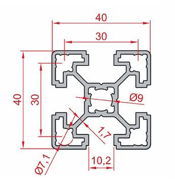
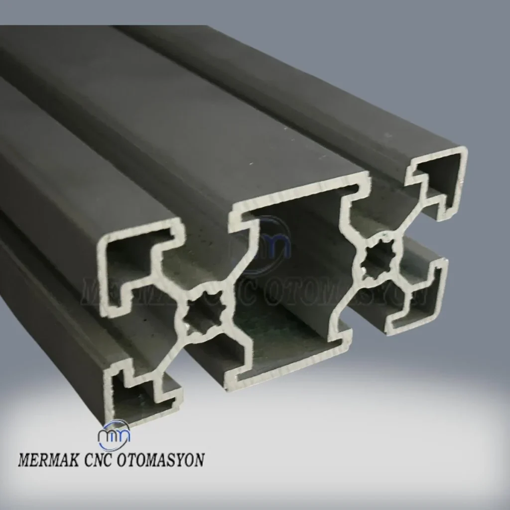
Sigma profiles are typically produced from high-strength aluminum alloys (mostly 6063-T5 or 6060-T6) using the extrusion method, and their surfaces are anodized to increase corrosion resistance and provide an aesthetic appearance. A characteristic feature of these profiles is their T-slot structures, into which various fasteners, nuts, and accessories can be easily inserted. These T-slots ensure the system’s flexibility and expandability, while also offering quick and easy assembly. Different cross-sectional dimensions (e.g., 20x20mm, 30x30mm, 40x40mm, 45x45mm, 60x60mm, 80x80mm) and various geometric forms allow engineers and designers to develop solutions suitable for a wide range of applications. Profile selection should be carefully made based on factors such as the project’s load-bearing capacity, rigidity requirements, aesthetic expectations, and environmental conditions. The quality of cutting and assembly are the most critical stages that ensure the theoretical advantages provided by these profiles translate into real-world performance.
Sigma Profile Cutting and Assembly: Operating Principles and Technical Data
The operating principle of sigma profiles is based on modularity and adaptability. The T-slots on the profiles allow for easy attachment of specially designed T-nuts, corner connectors, hinges, feet, and other accessories at any point along the profile. This achieves a fast and reconfigurable assembly process that does not require welding or special tools. This modular structure offers high flexibility against design changes and system expansions, which is a significant advantage, especially for prototyping and continuously evolving production lines.
Cutting Principles and Technical Details
Cutting sigma profiles is vital for the precision of the final product. Cutting quality directly affects ease of assembly and structural integrity.
- Saw Blade Selection: Circular saw blades specifically designed for aluminum profiles should be preferred. The tooth geometry (typically negative or zero rake angle), tooth count, and coating (Tungsten Carbide – HM/TC tips) of these blades must be suitable for the sticky nature of aluminum and ensure effective chip removal. Incorrect blade selection leads to burring, rough surfaces, and reduced blade life.
- Cutting Speed (RPM): High rotational speeds are recommended for cutting aluminum, but this varies depending on the profile’s cross-section and the saw blade diameter. Excessively low speeds can cause material tearing and strain on the blade, while excessively high speeds can increase friction, leading to heat buildup and material melting. Manufacturer recommendations should always be followed.
- Feed Rate: The speed at which the saw blade enters the profile affects cutting quality. A too-fast feed rate can cause burring and reduce cutting precision, while a too-slow feed rate can increase heat buildup and shorten blade life.
- Cooling and Lubrication: Heat control is crucial in aluminum cutting. Cutting fluids (lubrication or emulsion-based) or air cooling systems should be used to dissipate heat generated during cutting and to remove chips effectively. This improves both cutting quality and extends blade life.
- Cutting Precision and Tolerances: In industrial automation applications, tenths of a millimeter precision can be critical. Professional cutting machines should be able to cut within narrow tolerance ranges, such as +/- 0.1mm to +/- 0.2mm. For miter cuts, angular precision (e.g., +/- 0.05 degrees) is also of great importance.

Assembly Principles and Technical Details
The assembly of sigma profiles is as important as cutting for the system’s final performance and stability.
- Fastener Selection: The correct fasteners must be chosen according to project requirements.
- T-nuts: Used for standard connections. Various types are available (sliding, spring-loaded, impact-resistant).
- Corner Connectors: Used for joining profiles at right angles. Available in internal or external fitting types.
- Angle Connectors: Allow joining at specific angles (e.g., 45 degrees).
- Profile Connectors: Used to join profiles end-to-end or in a T-shape.
- Hinges, Feet, Wheels: Used to provide movable parts, support, and mobility.
- Tightening Torque: Overtightening or undertightening fasteners leads to structural weaknesses. The manufacturer-specified torque values for each fastener and screw must be adhered to. Using a torque wrench ensures consistent and reliable connections.
- Alignment and Miter Adjustment: During assembly, correct alignment of profiles relative to each other and precise angle adjustment (with spirit levels, squares, laser alignment tools) are critically important. Misalignment can lead to stresses, distortions, and premature fatigue in the system.
- Gap Control: Gaps that may occur at connection points can lead to vibration and loss of stability. It is important to ensure that fasteners are fully seated and that connections are gap-free.
- Structural Rigidity: In large or heavy-load-bearing structures, rigidity should be increased by using additional cross-bracing, support profiles, or gusset plates. The torsional and bending resistance of the profile must be calculated during the design phase.
| Parameter | Value/Description |
|---|---|
| Material Alloy | Aluminum 6063-T5 or 6060-T6 (Typically) |
| Surface Treatment | Anodized, Typically 10-20 microns thick |
| Standard Dimensions (mm) | 20×20, 30×30, 40×40, 45×45, 60×60, 80×80, 90×90 (and variations) |
| Cutting Tolerance (Dimensional) | +/- 0.1 mm to +/- 0.2 mm (With professional machines) |
| Angular Cutting Tolerance | +/- 0.05 degrees (For miter cuts) |
| Typical Fastener Torque | 8-12 Nm for M6 screw, 18-25 Nm for M8 screw (Varies by connection type) |
| Application Areas | Machine frames, conveyors, automation cells, workstations, safety barriers, robotic stands |
Sigma Profile Cutting and Assembly: On-Site Considerations
- Detailed Planning and Measurement Accuracy Before Cutting: The cutting length and angle of each profile must be determined with millimeter precision according to project drawings. Precision calipers, laser meters, or digital angle gauges should be used for measurement. A cutting plan (nesting) should be created to prevent material waste and minimize assembly errors, and profiles should be traceable with serial numbers or labels.
- Selection of Correct Equipment and Consumables: The calibration of the cutting machine and the condition of the saw blade are critically important. A dull or incorrectly toothed blade will reduce cutting quality and cause burring. The saw blade should be regularly sharpened or replaced. Ensure that cooling and lubrication systems are active and effective.
- Occupational Safety Measures: Appropriate Personal Protective Equipment (PPE) must be used during cutting and assembly. Safety glasses, gloves, hearing protection, and dust masks are indispensable. The cutting area should be well-ventilated, and chips should be regularly cleaned, which is important for both safety and cutting quality.
- Gradual Tightening and Alignment During Assembly: All fasteners should initially be hand-tightened only. Then, after the entire structure is brought into the desired position, the final torque values should be reached gradually and crisscross using a torque wrench. This prevents stresses that may occur during assembly and ensures the structure settles evenly. For large structures, checking each joint with a spirit level or laser alignment device helps detect potential deviations at an early stage.
- Structural Integrity and Rigidity Check: After assembly is complete, the overall rigidity and stability of the structure should be checked. Especially in applications where dynamic loads or vibrations are expected, the structure should be tested for any flexing, swaying, or noise at any point. If necessary, the structure should be reinforced by adding additional support profiles, cross-bracing, or vibration damping elements.
- Surface Protection and Cleaning: The anodized surfaces of profiles are sensitive to scratches. During assembly, avoid rubbing profiles on the ground, dropping tools, or contact with sharp objects. After assembly, cleaning profile surfaces with industrial cleaners to remove oil, dirt, and fingerprints is important for both aesthetic appearance and longevity.
Sigma Profile Cutting and Assembly: Common Problems and Solutions
Below are some common problems encountered in the installation of sigma profile systems and their solutions:
- Problem: Incorrect Cutting Lengths or AnglesDescription: Cutting profiles to dimensions different from those specified in the project leads to gaps in assembly, structural stresses, or parts not fitting together. Angular errors, especially in miter cuts, can cause the entire structure to be distorted.
Solution: Double-checking measurements before cutting and using precision measuring tools such as laser meters and digital angle gauges are essential. It is important to periodically calibrate the cutting machine and check the accuracy of its settings. Operator training and strict adherence to the cutting plan are required.
- Problem: Excessive Burring and Rough Cut SurfacesDescription: Burrs on the edges of cut profiles make assembly difficult, prevent fasteners from seating properly, and pose a risk of injury. Rough surfaces also detract from the aesthetic appearance.
Solution: Use a sharp circular saw blade with the appropriate tooth geometry and coating for aluminum. Cutting speed and feed rate should be adjusted according to manufacturer recommendations. Adequate cooling and lubrication (cutting fluid or air cooling) should be applied. Deburring (manual or automatic) must be performed after cutting.
- Problem: Gaps, Warping, and Structural Looseness in AssemblyDescription: Gaps, warping, or general looseness observed in the structure after assembly, where profiles do not fully join, reduce the system’s stability and load-bearing capacity. These problems become more pronounced in vibrating environments.
Solution: Ensure strict adherence to cutting tolerances. Ensure that fasteners (T-nuts, corner connectors, etc.) are of the correct type and quality. All connection bolts should be tightened with a torque wrench according to the manufacturer’s specified torque values. Alignment should be checked at each stage during assembly using spirit levels, squares, or laser alignment tools. If necessary, the structure can be strengthened with additional support profiles or gusset plates.
- Problem: Fasteners Jamming or StrippingDescription: T-nuts jamming in the profile channel or screws stripping prolongs assembly time and compromises connection reliability.
Solution: Use high-quality and correctly sized T-nuts and screws. Ensure T-nuts are inserted into the profile channel in the correct orientation. Prevent overtightening by using a torque wrench when tightening screws. Stripped screws or nuts should be replaced immediately. Some T-nuts have spring mechanisms to prevent slipping; these types of nuts can be preferred.
- Problem: Insufficient Resistance of the Structure to VibrationsDescription: Especially in systems with moving parts or machinery, the structure’s inability to adequately dampen vibrations can lead to performance degradation and fatigue failures.
Solution: Structural analyses should be performed during the design phase to determine vibration modes. More rigid profile cross-sections can be selected. The overall rigidity of the structure should be increased by adding cross-bracing, support profiles, and corner brackets. Vibration-damping feet or mounting elements can be used to isolate the system from ground vibrations.
- Problem: Surface Damage and CorrosionDescription: Scratches on the anodized surface of profiles during assembly or use reduce corrosion resistance and detract from the aesthetic appearance.
Solution: Be careful when handling and assembling profiles; prepare the work area before removing them from their protective packaging. Avoid rubbing sharp tools against profiles. Anodizing thickness or additional surface treatments suitable for environmental conditions (humidity, chemical vapor) can be preferred. Regular cleaning and maintenance help protect the surface.
Sigma Profile Cutting and Assembly: Conclusion and Expert Advice
In the complex and dynamic world of industrial automation, the correct cutting and assembly of sigma profile systems are fundamental steps for a project’s success. These processes not only ensure the physical integrity of a structure but also directly affect the machine’s precision, reliability, lifespan, and even the overall efficiency of the production line. As an expert field engineer, my advice is to approach these processes not as “simple assembly work” but as an integral part of engineering discipline. The accuracy of each cut, the torque value of each connection, and the alignment of each profile are reflections of the precision at the heart of the system.
The keywords for a successful application are detailed planning, correct equipment selection, and trained personnel. Comprehensive drawing analysis before cutting, accurate measurement techniques, and appropriate cutting machine settings allow you to eliminate errors on paper or during the first cut. During the assembly phase, the selection of quality fasteners, torque-controlled tightening methods, and continuous alignment checks guarantee the long-term durability and stability of the structure. It should be remembered that a small initial investment (a better saw, torque wrench, or operator training) will save you much larger costs (breakdowns, production losses, revisions) in the long run.
Furthermore, the modular nature of these systems allows for future modifications and expansions, so the quality of the initial assembly supports this flexibility. A loosely or incorrectly assembled system can create additional difficulties in future revisions. Therefore, paying utmost attention to sigma profile cutting and assembly in your projects will not only ensure the success of the current project but also build a solid foundation for your future automation needs. In the competitive industrial landscape, these “key considerations” should become standards to deliver high-quality and reliable automation solutions. Always aim for best practices, because excellence in industrial automation is hidden in the details. Request a quote on WhatsApp for your sigma profile needs.
FAQ
What are sigma profiles and what are they used for in industrial automation?
Sigma profiles are modular aluminum extrusion systems used to build frames for industrial machinery, conveyor systems, robotic cells, and safety enclosures. They feature T-slots that allow for easy, reconfigurable assembly without welding, using specialized fasteners like T-nuts and corner connectors.
Why is precision in sigma profile cutting and assembly so important for industrial applications?
Precision is crucial because incorrect cutting or assembly can lead to structural weaknesses, misalignment, reduced load-bearing capacity, and premature wear. Accurate cuts ensure proper fit, while correct assembly with specified torque values guarantees stability and longevity, directly impacting the overall performance and safety of industrial equipment.
What are the critical technical details for achieving high-quality sigma profile cuts?
Key considerations include selecting the right saw blade (Tungsten Carbide, negative/zero rake angle) for aluminum, optimizing cutting speed (RPM) and feed rate, and utilizing cooling/lubrication systems to prevent heat buildup and burring. Achieving dimensional tolerances of +/- 0.1mm to +/- 0.2mm and angular tolerances of +/- 0.05 degrees is essential.
What are the best practices for assembling sigma profiles to ensure structural integrity?
For assembly, select appropriate fasteners (T-nuts, corner connectors) based on application, adhere to manufacturer-specified torque values using a torque wrench, and ensure precise alignment using spirit levels or laser tools. Checking for gaps, reinforcing structural rigidity with cross-bracing, and performing post-assembly stability checks are also vital.
What are common problems encountered during sigma profile assembly and how can they be resolved?
Common problems include incorrect cut lengths/angles, excessive burring, structural looseness, fastener jamming/stripping, and inadequate vibration resistance. Solutions involve meticulous planning, using calibrated equipment, proper blade selection, controlled tightening, and structural analysis to add reinforcement or vibration damping.



