No products in the cart.
How to Select Ohm and Watt Values for Servo Drive Regenerative Resistors
Contents
Selecting the correct Ohm and Watt values for a servo drive regenerative resistor depends on the drive’s DC bus voltage, minimum resistance requirements, and the average and peak energy that needs to be dissipated during the braking cycle. Manufacturer catalogs and detailed system analyses form the basis of this selection; oversizing with a safety factor is always recommended.
Understanding Regenerative Resistors in Servo Drive Systems
In industrial automation systems, especially in motion control applications with high dynamic requirements, servo motors are frequently subjected to acceleration and deceleration cycles. When a servo motor decelerates or is driven by an external load, it acts like a generator, producing electrical energy. This generated energy is called regenerative energy. If this energy is not managed properly within the system, it can raise the servo drive’s DC bus voltage to dangerous levels, leading to an overvoltage error and potential damage to the drive.
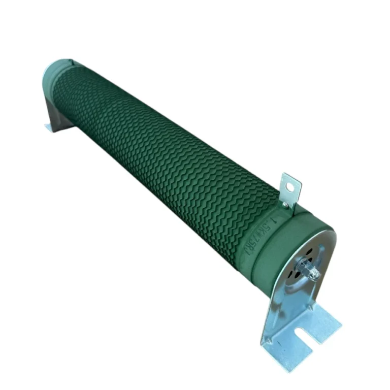
This is where the regenerative braking resistor comes into play. An internal or external braking chopper within the servo drive activates when the DC bus voltage exceeds a certain threshold, directing the excess energy to this resistor. The resistor converts the electrical energy into heat, dissipating it in a controlled manner and ensuring that the DC bus voltage remains within safe limits. This protects the drive and maintains the continuous dynamic performance of the system. The correct selection of the resistor’s Ohm and Watt values is critically important for the reliability and lifespan of the system.
Operating Principle and Technical Data for Regenerative Resistors
Regenerative resistor selection focuses on two main parameters: the Ohm (Ω) value and the Watt (W) value. These values are determined by the dynamic requirements of the servo system, the inertia of the motor and load, braking times, and the technical specifications of the drive.

Ohm (Ω) Value Selection:
The Ohm value of the resistor is directly related to the drive’s DC bus voltage and the current carrying capacity of its internal braking chopper. Every servo drive manufacturer specifies a minimum resistance value (Rmin) to protect its internal braking chopper and ensure efficient operation. Falling below this value can cause the chopper to draw excessive current and malfunction. If the resistance value is chosen too high, insufficient current will be drawn during braking, leading to an increase in DC bus voltage and an overvoltage error.
- Drive Manual: The first step is to consult the technical manual of the servo drive being used. The manual typically specifies the recommended resistance range or minimum resistance value clearly. This value defines the safe operating region of the braking chopper.
- DC Bus Voltage (Vdc): The braking chopper activates when the DC bus voltage exceeds a certain threshold (Vthreshold). This threshold is usually around 110-120% of the drive’s nominal DC bus voltage. The maximum current (Imax) that will flow through the resistor, and thus the resistance value, is related to this threshold voltage: R = Vthreshold / Imax_chopper. However, the Rmin value specified by the manufacturer usually provides a sufficient reference.
- Application Requirements: In some cases, for applications requiring very fast and intense braking, selecting a resistance close to the Rmin value provides more effective energy dissipation. However, this requires careful evaluation of the thermal capacity of both the drive and the resistor.
Watt (W) Value Selection:
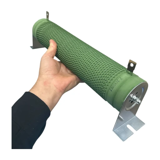
The Watt value of the resistor indicates the average power it needs to dissipate and its short-term peak power capacity. This depends on the system’s dynamics and operating cycle.
- Average Regenerative Power (Paverage): This is the most critical parameter. It is calculated by dividing the total amount of energy that needs to be dissipated over a complete operating cycle by the cycle time.
- Energy Calculation: Changes in the kinetic energy of the motor and load during deceleration, and changes in potential energy (for vertical movements), are considered. Kinetic energy: Ek = 0.5 * J * ω² (J: total inertia, ω: angular velocity). Potential energy: Ep = m * g * h. A portion of this energy is reduced by motor and drive losses, with the remainder going to the resistor for dissipation.
- Cycle Time (Tcycle): The duration of one complete operating cycle.
- Braking Time (tbraking): The duration during which braking is active.
- Duty Cycle: %DC = (tbraking / Tcycle) * 100. Average power is equal to the peak power multiplied by the duty cycle: Paverage = Ppeak * (%DC / 100).
Generally, the formula Paverage = (Eregenerative_total / Tcycle) is used. This value indicates the continuous power the resistor must withstand.
- Peak Regenerative Power (Ppeak): This is the maximum power the resistor is subjected to during short, intense braking moments. It can often be several times the nominal power of the motor. Most resistors can withstand short-term peak powers above their nominal Watt rating (pulse power rating). This value is directly related to the voltage applied to the resistor when the drive’s overvoltage threshold is reached, and the selected Ohm value: Ppeak = Vthreshold² / R.
- Safety Factor: A safety factor of usually 50% to 100% should be added to the calculated average Watt value. This provides protection against unexpected load changes, ambient temperature fluctuations, and resistor aging. For example, if the calculated average power is 100W, selecting a 150W or 200W resistor is safer.
- Thermal Management: The Watt value of the resistor also indicates how efficiently it can dissipate heat. Higher Wattage resistors generally have a larger surface area and better cooling capacity.
| Parameter | Value/Description |
|---|---|
| DC Bus Voltage (Vdc) | Nominal DC bus voltage of the drive (e.g., 300V, 540V). The regeneration threshold voltage is around 110-125% of this value. |
| Minimum Resistance (Rmin) | The lowest resistance value specified by the servo drive manufacturer to protect the internal braking chopper (e.g., 20Ω). |
| Average Regenerative Power (Paverage) | Average power (W) that needs to be dissipated over one cycle. Critical for continuous operation. |
| Peak Regenerative Power (Ppeak) | Maximum power (W) the resistor is subjected to during instantaneous, short-term braking. Related to the resistor’s pulse withstand capability. |
| Braking Cycle Time (Tcycle) | Duration of the entire operating cycle (seconds). Used in average power calculation. |
| Duty Cycle | Ratio of the time braking is active to the total cycle time (%). |
| Safety Factor | A safety margin of 50% – 100% added to the calculated Watt value. |
| Resistor Tolerance | Deviation rate of the selected resistor from its nominal value (e.g., ±5%). |
Field Considerations for Regenerative Resistors
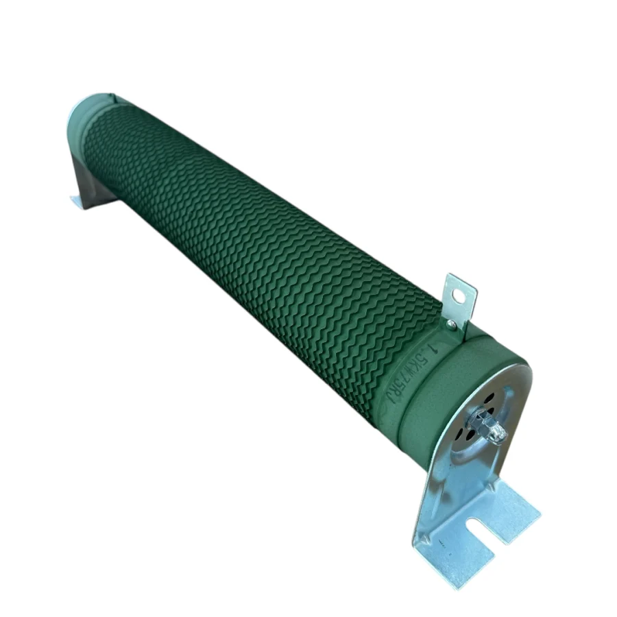
- Mounting Location and Cooling: Regenerative resistors generate a significant amount of heat during operation. Therefore, it is crucial that the mounting location is well-ventilated, sufficient clearance is left around it, and forced cooling (fan) is used if necessary. Insufficient cooling in enclosed panels shortens the resistor’s lifespan and can create a fire hazard due to overheating. Attention should be paid to the resistor’s outer surface temperature, and warning labels should be used to prevent contact risk.
- Cabling and Connections: The cable cross-section between the resistor and the drive must be appropriate for the maximum current it will carry, and the cable length should be kept as short as possible. Long cables can cause voltage drops and electrical noise (EMI/RFI). Connection points must be tight and reliable; loose connections can lead to arcing and power loss. Vibration-resistant terminals should be preferred in industrial environments.
- Environmental Conditions and IP Rating: Dust, humidity, chemical vapors, and temperature variations in the resistor’s operating environment must be considered. Resistors with an appropriate IP protection class for the environmental conditions (e.g., aluminum-housed, IP65) should be preferred. Excessive humidity or corrosive gases can damage the resistor material.
- Thermal Protection and Safety: For high-power resistors, internal thermal switches (NC contact) can be used to prevent overheating. These switches can send a warning signal to the drive or PLC, stopping the system or interrupting the braking process if the resistor exceeds a certain temperature threshold. This ensures the safety of both the resistor and surrounding equipment.
- Resistor Type and Material: Wire-wound or strip resistors are commonly used for industrial applications. Aluminum-housed resistors are preferred because they dissipate heat more efficiently and are mechanically more robust. The material used in the resistor’s construction must be resistant to vibration, humidity, and temperature cycles.
- Drive Compatibility and Settings: Ensure that the selected resistor is fully compatible with the servo drive’s braking chopper module. Some drives may require internal parameter adjustments when an external resistor is connected (e.g., braking chopper threshold voltage, braking power limits). Correctly setting these parameters ensures optimal system performance and safety.

Common Issues and Solutions
Errors in regenerative resistor selection or application can lead to various problems in the system. Here are some common issues and their suggested solutions:
- Overvoltage Fault – On the Drive:
- Problem: The drive frequently displays a “DC Bus Overvoltage” error.
- Possible Causes:
- Resistor Ohm value is too high: Insufficient current flows through the resistor, preventing effective dissipation of regenerative energy.
- Resistor Watt value is insufficient: The resistor overheats, and its resistance value changes (usually increases) or it burns out, reducing its effectiveness.
- Braking chopper is faulty: The drive’s internal or external braking module is not engaging.
- Braking time is too short: Very rapid decelerations cause more energy to be loaded onto the resistor than it can handle instantaneously.
- Solution:
- Check the resistor’s Ohm value and select a value closer to, but greater than, the drive’s Rmin value.
- Increase the resistor’s Watt value and ensure adequate cooling.
- Test the drive’s braking chopper or consult an authorized service center.
- If possible, increase the braking time by extending the deceleration ramps.
- Resistor Overheating or Burning Out:
- Problem: The resistor overheats excessively, changes color, emits an odor, or is physically damaged (burns out).
- Possible Causes:
- Resistor Watt value is insufficient: It cannot handle the average regenerative power expected from the system.
- Inadequate cooling: Insufficient airflow around the resistor or excessively high ambient temperature.
- Incorrect duty cycle calculation: Braking time or frequency is higher than expected.
- Resistor Ohm value is too low: Too much current flows through the resistor (though this usually causes an overcurrent fault in the drive).
- Solution:
- Select a higher Watt value resistor (50-100% more than the calculated average power).
- Improve the resistor’s mounting location, increase ventilation, or add fan cooling.
- Re-analyze the system’s actual operating cycle (braking frequency and duration) and revise the Watt value accordingly.
- Ensure the Ohm value is kept above the drive’s Rmin value.
- Overcurrent Fault – In the Braking Chopper Circuit:
- Problem: The drive displays a “Braking Chopper Overcurrent” or similar error.
- Possible Cause: The resistor Ohm value is lower than the drive’s minimum resistance value (Rmin).
- Solution: Check the resistor’s Ohm value. Ensure you have selected a resistor value greater than or equal to the Rmin value specified in the drive manual.
Expert Advice for Industrial CNC Applications
The correct selection of Ohm and Watt values for a servo drive regenerative resistor is vitally important for the reliability, efficiency, and longevity of industrial automation systems. This selection should be based not only on theoretical calculations but also on a comprehensive analysis of the system’s actual operating conditions, load dynamics, and environmental factors. It is crucial to remember that an inadequately selected resistor can lead to frequent system shutdowns, drive failures, and even safety risks, while an oversized resistor can result in unnecessary costs and space consumption.
As experts, we always recommend incorporating a safety margin in this regard. Adding a safety factor of at least 50%, and preferably up to 100%, to the calculated average Watt value ensures that the system is more resilient against unexpected loads, ambient temperature changes, or potential performance degradation over time. Furthermore, the physical mounting and cooling arrangements of the resistor are as important as the selected values. A poorly ventilated or inadequately cooled resistor can experience performance issues and a shortened lifespan, even if it has the correct values.
Always adhere strictly to the minimum resistance values and recommendations specified in the servo drive manufacturer’s technical manual. For complex or critical applications, seeking assistance from a motion control specialist or the manufacturer’s technical support team is the most appropriate approach to prevent potential problems and guarantee optimal system performance. Remember, a correctly selected regenerative resistor is more than just a component; it is one of the fundamental guarantees for the healthy operation of the drive and motor, which are the heart of the entire automation system. By paying attention to these details, it is possible to build long-lasting, safe, and efficient industrial systems.
For inquiries about servo drive components or industrial CNC router machines, please request a quote on WhatsApp.