



































































































































When a servo motor stops suddenly, the drive typically alarms due to abrupt changes in critical parameters such as deviation from the expected motion profile, excessive acceleration/deceleration, position error, overcurrent, or regenerative voltage increase. This is a safety mechanism designed to ensure system stability and protect the motor and mechanical components.
Understanding Servo Drive Alarms During Sudden Motor Stops
In industrial automation systems, servo motors are indispensable for precise motion control. A sudden stop of a servo motor leads to significant deviations in the parameters controlled by the drive (servo drive or servo amplifier). These deviations trigger the drive’s internal safety protocols, causing it to issue an alarm. This alarm indicates a potential fault, mechanical overload, or a misconfigured system. Key reasons include position error, speed deviation, overcurrent, and overvoltage due to regenerative energy.
Servo drives are closed-loop control systems that continuously monitor the motor’s position, speed, and torque. This monitoring is performed via feedback devices such as an encoder or resolver mounted on the motor. The drive compares the commanded signal (target position/speed) with the motor’s actual position/speed. When a sudden stop command is issued or the motor stops unexpectedly, the change in speed and position due to the motor’s inertia may not align with the drive’s expected ideal profile. These discrepancies cause the drive to generate an alarm when they exceed specific error tolerances.
Operating Principles and Technical Data Behind Servo Drive Alarms
Servo drives utilize complex algorithms and electronic circuits to precisely control motor movement. The technical principles underlying an alarm during a sudden stop are as follows:
- Position Error: The drive continuously calculates how far the motor is from its target position. During sudden stops, it’s impossible for the motor to instantly reach the desired position due to its inertia, or if it stops due to a mechanical jam, the position difference (error) between the drive and the motor exceeds a certain threshold (position error limit). This causes the drive to issue a “Position Error” or “Tracking Error” alarm. Especially in high-inertia systems, sudden stops can easily trigger this error.
- Speed Deviation: The drive also monitors the motor’s instantaneous speed. When a sudden stop command is given, the motor’s speed is expected to drop to zero very quickly. However, if control parameters (especially PID gains) are not correctly tuned, or if the motor’s load is too high, the speed profile may deviate from the expected curve. If the motor’s speed shows a change outside the drive’s tolerance range, a “Speed Deviation” alarm may occur.
- Overcurrent: To stop a servo motor suddenly, a high torque (braking torque) must be applied. To generate this high torque, the drive may send very high currents to the motor. If this current value exceeds the nominal current limits of the drive or motor, the drive issues an “Overcurrent” alarm to protect the motor and its power electronics, shutting down the system. This usually occurs due to very aggressive deceleration ramps or mechanical jams.
- Overvoltage / Regenerative Energy: The motor acts like a generator, converting mechanical energy into electrical energy. Especially when decelerating high-inertia loads suddenly, the motor’s kinetic energy is converted into electrical energy, increasing the drive’s DC bus voltage. If this voltage exceeds the drive’s permissible maximum DC bus voltage, the drive issues an “Overvoltage” or “Regenerative Error” alarm. An external regenerative resistor (braking resistor) is typically used to safely dissipate this energy. An undersized or faulty braking resistor can lead to such alarms.
- Torque Limit Exceeded: Drives often software-limit the maximum torque a motor can produce. If the torque required to overcome the motor’s inertia during sudden stops exceeds this software limit, the drive may issue a torque limit alarm.
- Mechanical Problems: If there is a sudden jam, breakage, or excessive friction in the motor or its connected mechanical system (gearbox, belt, shaft, bearings, etc.), the motor will stop unexpectedly. The drive detects that the motor cannot respond to commands, triggering one of the position, speed, or current errors mentioned above.
| Parameter | Value/Description |
|---|---|
| PID Gains | Kp (Proportional), Ki (Integral), Kd (Derivative) values. Directly affect speed and position error during sudden stops. |
| Position Error Limit | Maximum position difference the drive can tolerate (usually in encoder counts). Triggers an alarm if exceeded. |
| Maximum Current Limit | Maximum peak current the drive can supply to the motor (Amperes). Can be exceeded during sudden braking. |
| DC Bus Voltage Limit | Maximum permissible voltage on the drive’s DC bus (Volts). Increases with regenerative energy. |
| Deceleration Time (Ramp Time) | Minimum time required to go from a certain speed to zero (seconds). Being too short is a common cause for alarms. |
| Encoder Resolution | Number of pulses generated by the motor per revolution (PPR or counts). Determines error detection sensitivity. |
| System Inertia Ratio | Ratio of load inertia to motor inertia. High ratios make control difficult during sudden stops. |
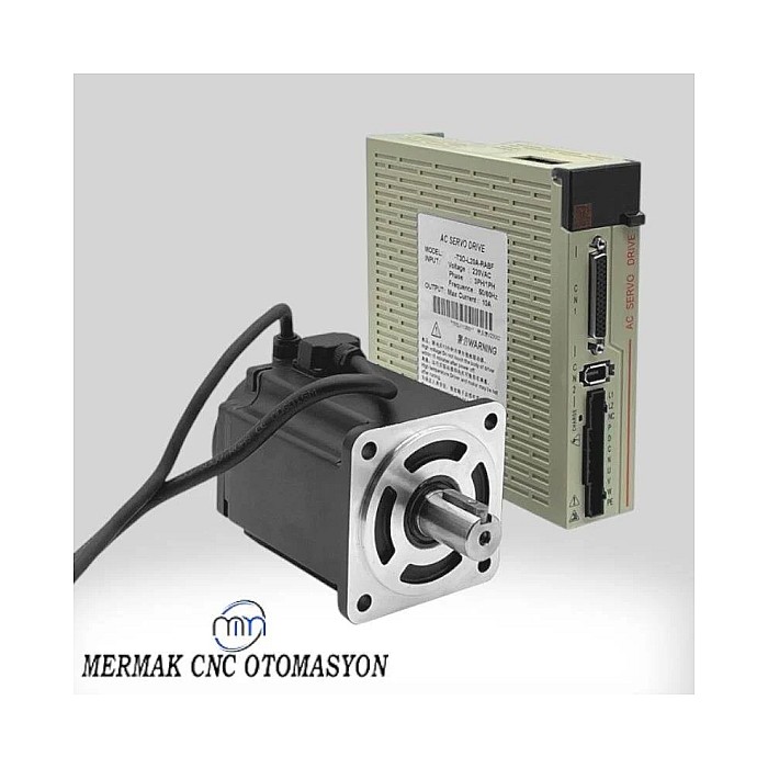
Key Considerations in Industrial Applications
- Load and Inertia Matching: When selecting a servo motor and drive, the inertia of the connected load is critical. The ratio between the motor’s inertia and the load’s inertia (typically acceptable between 1:1 and 1:10) directly affects sudden acceleration/deceleration performance. Motors controlling high-inertia loads generate more regenerative energy and require higher torque during sudden stops. Therefore, it is crucial to ensure that the motor and drive are selected to match the load profile.
- Regenerative Braking and Resistor Sizing: A regenerative braking resistor is used to safely dissipate the energy generated when the motor acts like a generator during sudden stops. The power (Watts) and resistance value (Ohms) of this resistor must be correctly sized according to system requirements. An undersized or faulty resistor can cause the drive’s DC bus voltage to rise to critical levels, leading to an overvoltage alarm. Ensure the resistor’s connections are secure and its thermal protection is functional.
- Drive Parameter Settings (PID Tuning): The PID (Proportional-Integral-Derivative) gains of the servo drive determine the system’s dynamic response. Incorrectly tuned PID gains can cause the motor to oscillate, overshoot the target position, or respond too slowly during sudden stops. Aggressive gains lead to overcurrent or vibrations, while low gains increase position error. For sudden stop scenarios, correctly setting acceleration/deceleration ramps and speed loop gains is essential for stable and error-free system operation. The drive’s auto-tuning functions can often assist in this process.
- Mechanical System Inspection: The mechanical components connected to the motor (gearbox, coupling, belt, ball screw, linear guides, etc.) should be checked for backlash, excessive friction, jamming, or damage. During sudden stops, such mechanical problems can prevent the motor from moving as expected, causing the drive to issue a position or torque error. Regular maintenance and inspection of mechanical components play a critical role in preventing these alarms.
- Feedback System (Encoder/Resolver) Health: Breaks in cables, loose connections, electrical noise (EMI), or a fault in the encoder or resolver itself can prevent the drive from accurately sensing the motor’s actual position or speed. This can lead to the drive making incorrect interpretations during sudden stops and issuing an alarm. Ensure the encoder cabling is properly grounded and shielded, and that connectors are secure.
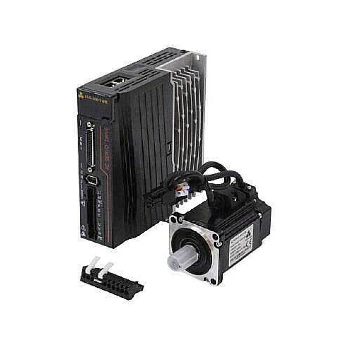
Common Issues and Industrial Solutions
A servo drive alarming during a sudden stop often points to specific fault scenarios. Here are common issues and their respective solutions:
- Issue: “Position Error” or “Tracking Error” alarm during a sudden stop.
- Possible Causes: Insufficient PID gains, mechanical backlash/jamming, encoder fault/noise, motor unable to track the load correctly.
- Solution:
- Optimize the drive’s PID gains. Start with the auto-tuning function and then make fine adjustments manually. Increasing speed loop gains can often help.
- Inspect and eliminate backlash or jams in the mechanical system. Review the condition of couplings, gearboxes, and moving parts.
- Check encoder connections and cabling. Ensure proper shielding against noise. Test the encoder itself for faults.
- Slightly extend deceleration ramps to allow the motor to stop more smoothly.
- Issue: “Overcurrent” or “Overtorque” alarm during a sudden stop.
- Possible Causes: Very short deceleration time, mechanical jamming, torque requirement exceeding the motor’s nominal current, incorrect motor/drive sizing.
- Solution:
- Increase the deceleration ramp time to allow the motor to stop over a longer period. This will reduce the instantaneous torque requirement.
- Check for and eliminate any jamming or excessive friction in the mechanical system.
- Verify that the application’s required torque does not exceed the motor’s continuous and peak torque capacity. Consider using a larger motor or drive if necessary.
- Check the drive’s current limit settings, but these should generally remain at factory defaults for motor safety.
- Issue: “Overvoltage” or “Regenerative Error” alarm during a sudden stop.
- Possible Causes: Undersized or faulty regenerative braking resistor, excessively fast deceleration ramps, high-inertia load.
- Solution:
- Check the connections, resistance, and power rating of the regenerative braking resistor. Ensure the resistor is robust and matches the nominal values. If necessary, use a braking resistor with higher power or lower resistance (provided it is compatible with the drive).
- Extend deceleration ramps to allow the motor to stop more slowly. This reduces the peak of the generated regenerative energy.
- Monitor the drive’s DC bus voltage to help identify the source of the problem.
- Issue: “Speed Deviation” alarm during a sudden stop.
- Possible Causes: Incorrect PID gains (especially speed loop), sudden load changes, encoder error.
- Solution:
- Carefully adjust the speed loop gains (Kp, Ki). Auto-tuning is usually a good starting point.
- Check for sudden load changes or vibrations.
- Ensure the encoder is functioning correctly and the signal quality is good.
Expert Advice for Industrial CNC Systems
Servo drives alarming during sudden motor stops is a direct result of the system’s precise nature and its inherent safety mechanisms. These alarms are often not merely indicators of a fault but rather warning signals that the system has deviated from its expected operating conditions, indicating a potential problem. As an expert in industrial automation, it is essential to approach such situations systematically to identify the root cause, rather than panicking.
First, correctly interpreting the specific alarm code displayed by the drive and consulting the manufacturer’s manual is the initial step. Subsequently, systematically checking the mechanical, electrical, and software parameters detailed above is crucial. It is important to remember that the performance of a servo system depends on the harmonious operation of the motor, drive, mechanical components, and control software as a whole. A single incorrect parameter setting or a minor overlooked mechanical backlash can destabilize the entire system.
As expert advice, during the commissioning of any servo system or when performance issues arise, it is vital to implement a detailed PID tuning process, ensure the regenerative braking resistor is correctly sized and connected, not neglect periodic maintenance of the mechanical system, and ensure encoder cabling is protected from EMI. Furthermore, a thorough understanding of the system’s dynamics and load profile is a critical step in minimizing the likelihood of alarms during sudden stops. If necessary, using slower deceleration ramps can reduce stress on the system, extending the lifespan of both the motor and the drive. In complex situations, seeking manufacturer support or assistance from an experienced automation engineer is the most appropriate approach.
For reliable industrial CNC router components and expert technical support, request a quote on WhatsApp from Mermak CNC.