



































































































































In industrial automation systems, particularly with CNC (Computer Numerical Control) machines, the phenomenon of circles appearing oval during cutting operations can lead to significant quality issues in manufacturing processes that demand precision and accuracy. This directly impacts the functionality, assemblability, and aesthetic appearance of the final product. An oval shape in circle cutting signifies an elliptical form resulting from an ideal circle being stretched or compressed along a specific axis. This deviation is often visible to the naked eye and can be clearly detected with measuring instruments. Fundamentally, it stems from inconsistencies in motion control, repeatability, or accuracy in one or more axes of the machine performing the cutting operation, or in the cutting parameters themselves. These inconsistencies can originate from mechanical, electrical, or software issues, and typically arise from a complex combination of factors. In industry, especially in fields such as metalworking, woodworking, plastic processing, and composite material cutting, this type of problem can be encountered when performing circle cutting with various technologies like laser cutting, plasma cutting, waterjet cutting, and CNC router milling. Each cutting technology has its own specific precision requirements and potential sources of error. Ovality not only degrades the quality of the final product but also leads to material waste, extended production times, and consequently, increased costs. Therefore, understanding the root causes of such problems and developing effective solutions is of paramount importance for industrial automation engineers and field technicians.
Understanding Ovality in Circle Cutting: Causes and Technical Data
The underlying reasons for ovality in circle cutting are generally related to the interaction of the mechanical, electrical, and software components of automation systems. Any malfunction in these components can lead to distortions in the cutting geometry. Below, the main technical principles and factors contributing to these problems are detailed:
1. Mechanical Backlash and Precision Losses:
- Ball Screws and Nuts: Backlash between the ball screws and nuts, which provide axial movement in CNC machines, causes errors where the tool is not in the desired position during direction changes. This backlash becomes particularly pronounced during circular interpolation, where axes must continuously change direction, leading to the circle being elongated along one axis. Worn ball screws or loose nuts exacerbate this backlash.
- Linear Guides and Bearings: Wear, contamination, or loose mounting in the linear guide systems where the tool moves can create lateral play on the guides. This play causes the tool to deviate under cutting forces, distorting the circular form.
- Reducers and Couplings: Backlash in reducers or couplings that transmit power from servo motors to ball screws or other moving parts also leads to delays and precision losses in motion transmission.
- Tool Holders and Spindle Precision: In milling operations, runout of the tool holder or spindle causes the cutting tool to deviate from its center, contributing to the circle appearing oval. Worn spindle bearings trigger this problem.
2. Axial Speed and Acceleration Differences:
- Servo Motor Tuning: In CNC systems, each axis is controlled by independent servo motors. Incorrect tuning of these motors’ PID (Proportional-Integral-Derivative) parameters can cause speed and acceleration mismatches between axes. In circular interpolation, the X and Y axes must move simultaneously and synchronously. If one axis responds slower or accelerates faster than the other, this leads to the circle becoming oval.
- Friction Differences: If friction coefficients in axial motion systems vary between axes (e.g., one axis being dirtier or less lubricated), servo motors may respond differently to the same command.
3. CNC Control System and Software Errors:
- Interpolation Algorithms: CNC controllers generate circular movements using G-code commands as a series of short linear segments (interpolation). The precision and computational capacity of the controller’s interpolation algorithm can affect the accuracy of the circular form, especially at high speeds.
- G-Code Programming Errors: Incorrect entry of center point or endpoint coordinates in circular interpolation (G02/G03) commands directly results in an erroneous circle form.
- Kerf Compensation: In cutting technologies like laser, plasma, and waterjet, if the width of the cutting jet or laser beam (kerf) is not accounted for or is compensated incorrectly, the final cut dimension and geometry can be affected. Incorrect kerf compensation can cause the circle to deviate from its nominal size, leading to an oval appearance.
4. Tool Wear and Cutting Parameters:
- Cutting Tool Wear: In milling or turning operations, wear of the cutting tool distorts the geometry of the cutting edge and changes cutting forces. This makes it difficult for the tool to follow the desired path on the material, leading to ovality.
- Cutting Speed and Feed Rate: Inappropriate cutting speed and feed rate for the material, tool type, and cutting technology can lead to irregularities in cutting forces, vibrations, or tool deflections. Especially at low feed rates or excessively high speeds, the tool’s stability can be compromised.
- Nozzle Wear/Contamination (Laser/Plasma/Waterjet): Contamination of the laser nozzle or wear of the plasma/waterjet nozzle directly affects cutting quality and the accuracy of the cutting line. This can cause the cutting kerf to become irregular and the circle to appear oval.
5. Material Properties:
- Material Homogeneity and Stresses: Internal stresses within the material being cut or lack of material homogeneity (e.g., areas of different density, inclusions) can alter the material’s response during cutting. Cutting forces can release these stresses, causing the material to deform and the circle to become oval.
- Material Thickness and Flatness: Irregularities in material thickness or improper seating of the material on the table can cause the tool to cut at different depths, leading to geometric deviations.
6. Vibrations and Environmental Factors:
- Machine Vibrations: Vibrations originating from the machine itself, other nearby machines, or a weak foundation can destabilize the tool or workpiece during cutting, affecting circular accuracy.
- Temperature Changes: Temperature variations in the ambient environment or machine components can cause metal parts to expand or contract, altering mechanical clearances or axial alignment.
| Parameter | Value/Description |
|---|---|
| Axial Backlash Tolerance | Should generally be below 0.005 mm. Exceeding this increases the risk of ovality. |
| Servo Tuning Precision | Synchronization deviation between axes should be minimal. |
| Tool Runout | Maximum runout of the cutting tool should be within tight tolerances. |
| Cutting Speed Deviation | Difference between programmed and actual speed should not exceed 2%. |
| Material Homogeneity Factor | Variations in material density and hardness can impact cut quality. |
| Vibration Amplitude | Maximum vibration amplitude on the spindle or table should be controlled. |
| Kerf Compensation Accuracy | Kerf compensation should be applied with a deviation of no more than 1% from the actual kerf value. |
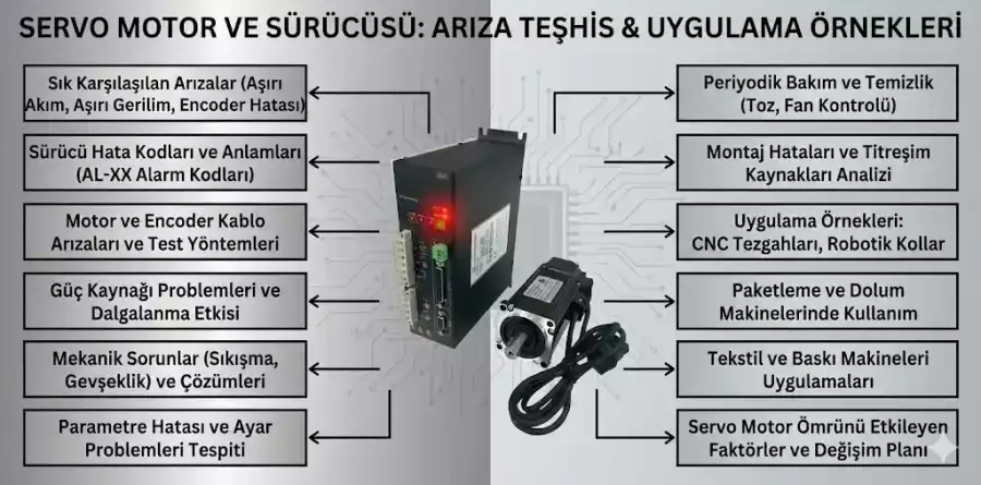
Practical Considerations for Industrial Environments
- Periodic Mechanical Maintenance and Inspection:
All moving axes of the machine, including ball screws, linear guide rails, bearings, and reducers, must be regularly inspected and cleaned. Worn or loose parts should be replaced or tightened immediately. Backlash calibration on ball screws, in particular, should be performed at regular intervals and according to the machine manufacturer’s recommendations. These checks are vital for maintaining the machine’s mechanical precision and preventing potential ovality issues.
- Axial Calibration and Servo Tuning:
Calibration of the X, Y, and Z axes of CNC machines is critical for motion accuracy and repeatability. Periodic checks of axial accuracy and circular interpolation performance should be conducted using precise measurement methods such as laser interferometry or ballbar tests. The PID parameters of servo motors must be correctly tuned to optimize the response time, speed, and acceleration of each axis. Ensuring synchronization between axes is a key factor in preventing ovality, especially in circular movements.
- Monitoring Cutting Tool and Nozzle Condition:
For machining methods like milling, the wear condition of cutting tools should be regularly checked, and worn tools replaced promptly. Spindle runout should be measured to ensure it remains within acceptable tolerances. For laser, plasma, or waterjet cutting, nozzles should be frequently inspected for signs of wear, contamination, or clogging, and cleaned or replaced as needed. A worn nozzle can irregularize the cutting kerf, leading to ovality.
- Material Preparation and Clamping:
Ensure that the material to be cut is placed flat and stress-free on the table. Surface flatness and thickness homogeneity of the material should be checked. Materials with internal stresses or warpage can deform during cutting, causing ovality. Secure clamping of the material (e.g., with a vacuum table, vises, or fixtures) prevents it from moving or vibrating under cutting forces.
- Program Optimization and Cutting Parameters:
Ensure that circular interpolation commands (G02/G03) in the CNC program (G-code) are correctly written and that center point/endpoint coordinates are accurate. Parameters such as cutting speed, feed rate, and spindle RPM should be optimized according to the material type, thickness, and cutting tool characteristics. Incorrect kerf compensation settings should be checked and adjusted to the actual cutting width. Creating a smoother cutting path by avoiding unnecessary acceleration/deceleration zones can improve circular accuracy.
- Environmental Control and Vibration Isolation:
Temperature and humidity changes in the machine’s environment can affect the expansion/contraction rates of machine components. If possible, environmental conditions should be stabilized. Ensure the machine is mounted on a solid foundation and that vibrations from other nearby machines are isolated. Vibration-damping feet or special foundation designs can help in this regard. Vibrations can cause instantaneous deviations of the tool or workpiece, leading to ovality in the circle.

Common Problems and Solutions
For industrial automation specialists and technicians encountering ovality issues in circle cutting, the most common scenarios and practical solutions are listed below:
- Problem: The cut circle appears longer or shorter, especially along the X-axis.
Solution: This usually indicates mechanical backlash or servo motor tuning issues in the X-axis. Inspect the X-axis ball screw, nut, linear guides, and bearings. Tighten loose connections and replace worn parts. Check and update backlash compensation values for the X-axis in the CNC controller. Additionally, re-tune the PID parameters of the X-axis servo motor to synchronize its response time and acceleration with other axes.
- Problem: The start and end points of the cut do not precisely meet, creating a “step” or gap at the circle’s junction.
Solution: This typically indicates that backlash in the axes is not sufficiently compensated. Since the axes must change direction at the start and end of the cut, backlash becomes evident at this point. Measure axial backlash values (e.g., with a dial indicator) and update the compensation values in the CNC controller accordingly. Also, review the tool’s kerf compensation settings and the start/end point transition strategies. In some cases, programming techniques that overlap the start and end of the cutting path can mitigate this problem.
- Problem: Irregularities or roughness are observed on the cutting surface along with ovality.
Solution: This suggests that the cutting tool (for milling) or nozzle (for laser/plasma/waterjet) is worn, or that cutting parameters (speed, feed, power) are incorrectly set. Inspect the cutting tool and replace it if necessary. Measure spindle runout. For laser/plasma/waterjet systems, check, clean, or replace the nozzle and focusing lens. Optimize cutting speed, feed, and power settings suitable for the material type and thickness. Ensure adequate cooling/lubrication fluid supply.
- Problem: Ovality ratios vary for circles of different diameters or in different materials.
Solution: This can be due to internal stresses in the material, different thermal expansion coefficients, or cutting parameters not being sufficiently adapted to material properties. Apply pre-processing treatments like annealing to relieve internal stresses in the material before cutting. Create and implement specific cutting parameter tables for different materials. For large diameter circles, the overall geometric accuracy of the machine becomes more prominent; therefore, check the machine’s general calibration. For small diameter circles, tool or nozzle precision becomes more critical.
- Problem: Vibrations occur when the machine reaches a certain point or a specific axis moves, leading to ovality.
Solution: Identify the source of the vibrations. This could be a loose machine part, a worn bearing, an unbalanced spindle, or even a weak foundation. Consider using vibration-damping feet or reinforcing the machine’s foundation. Check the servo motor settings; overly aggressive PID settings can also cause vibrations. Adjust cutting parameters (speed, feed) to reduce vibrations. Check the rigidity of the tool holder and the tool itself.
Expert Advice for Maintaining CNC Precision
The issue of ovality in circle cutting within industrial automation systems often stems from a complex interaction of mechanical, electrical, and software components, rather than a single factor. Therefore, adopting a holistic and systematic approach is essential for resolving the problem. From an expert’s observation in the field, the most common root causes of such precision losses are mechanical wear and backlash that develop over time, along with inadequate or incorrect tuning of servo control systems. Factors such as aging machine fleets, neglected periodic maintenance, or a failure to re-optimize parameters when transitioning to new materials or processes can trigger ovality problems.
As expert advice, I would first emphasize the critical importance of strictly adhering to the periodic maintenance and calibration routines recommended by the machine manufacturer. Regular inspection and elimination of backlash in ball screws, linear guides, and reducers play a crucial role in preserving circular accuracy. Secondly, it is vital to ensure that the servo motor tuning for each axis is optimal and that inter-axis synchronization functions correctly. Advanced diagnostic tools like ballbar tests are indispensable for comprehensively evaluating the machine’s geometric accuracy and circular interpolation performance. Thirdly, the condition of the cutting tool or nozzle and the correct adjustment of cutting parameters according to material and process specifications directly impact geometric accuracy alongside surface quality. Regular training for operators and maintenance technicians in these areas will enhance their ability to detect and resolve problems at an early stage. Finally, within the scope of Industry 4.0 principles, continuous monitoring and analysis of machine performance data (predictive maintenance) will maximize production continuity and quality by enabling the prediction of potential problems before they arise and the implementation of preventive measures. This proactive approach will both reduce costs and ensure the sustainable precision of industrial automation systems.
FAQ
What are the main reasons for circles appearing oval in CNC cutting?
Oval shapes in CNC circle cutting are primarily caused by mechanical backlash in ball screws and linear guides, incorrect servo motor tuning, worn cutting tools or nozzles, G-code programming errors, and material inconsistencies. Environmental factors like vibrations and temperature changes can also contribute.
How can I prevent oval shapes when cutting circles on my CNC machine?
To prevent ovality, implement a strict periodic maintenance schedule for mechanical components, including checking and calibrating backlash. Ensure proper servo motor tuning for synchronized axis movement. Regularly inspect and replace worn cutting tools or nozzles, and optimize cutting parameters for each material. Securely clamp the workpiece and control environmental factors like vibrations and temperature.
What should I do if the ovality is more pronounced along one specific axis?
If circles are oval along a specific axis (e.g., X-axis), check for backlash in that axis's mechanical components (ball screw, linear guides) and verify servo motor tuning. Use a dial indicator to measure backlash and update compensation values in the CNC controller. Re-tune PID parameters for better axis synchronization.
What if the cut circles are not only oval but also have a rough surface finish?
Rough cutting surfaces with ovality often indicate worn cutting tools, damaged nozzles, or incorrect cutting parameters. Inspect and replace worn tools or clean/replace nozzles. Optimize cutting speed, feed rate, and power settings for the specific material and thickness. Ensure adequate cooling/lubrication.
Why does the ovality change when cutting different circle sizes or materials?
Variations in ovality across different circle diameters or materials suggest issues with material properties (internal stresses, homogeneity) or cutting parameters not being adapted. Consider pre-treating materials to relieve stress. Develop and use specific cutting parameter tables for different materials and thicknesses. For large circles, check overall machine geometric accuracy; for small circles, focus on tool/nozzle precision.