
No products in the cart.
%47 Discount


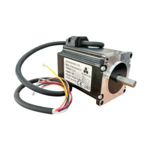
Nema 23 Step Motor 1.5 Nm
Original price was: 31.20$.16.46$Current price is: 16.46$.
Bipolar hybrid step motor designed for precise angular positioning and speed control in industrial automation systems.
Out of stock
🔥 Special for Today Only %47 Discount Opportunity!📦 Category: 57x57 mm Stepper Motors and Drivers
Mermak assuranceFrom factory to end user · importer / main dealer · strong stock
ImporterMain dealer / distributorStrong stockGood priceCorporate invoice
Contact us for stock information · 14-day return for standard unused products; conditions may vary for custom size/cut products.
Nema 23 Step Motor 1.5 Nm
INDUSTRIAL AUTOMATION PARTS | SUPERIOR PERFORMANCE SERIES
Detailed Product Review
The JSS-MOTOR brand NEMA 23 1.5 Nm Step Motor is a bipolar hybrid step motor designed for applications requiring angular positioning and speed control in industrial automation systems. This motor utilizes electromagnetic principles to convert electrical energy into precise and repeatable mechanical rotational motion. Sequential pulses applied to the windings on the stator interact with the rotor’s magnetic field, causing the rotor to rotate at specific angles (step angle). This discrete motion control offers high positioning accuracy even in open-loop systems, minimizing the need for feedback mechanisms. The NEMA 23 standard defines the motor’s mounting flange size as a 2.3-inch (approx. 57 mm) square, ensuring mechanical compatibility with standard mounting areas in industrial machinery. The 1.5 Nm holding torque indicates the motor’s ability to resist external loads and maintain its position at any step when energized, a critical feature for applications where the workpiece must remain stationary during processing. The 4.2A nominal current rating specifies the maximum current the motor windings can continuously handle without exceeding thermal limits, while the 6.72W power output indicates the mechanical work capacity the motor can produce at a given speed.
The structural components of this step motor are manufactured from industrial-grade materials to ensure long-lasting and reliable performance. Stator and rotor laminations are made from high-permeability silicon steel for efficient torque production and low hysteresis loss. The windings consist of high-temperature resistant enameled copper wires, supported by special insulation materials to enhance thermal stability. The motor housing is typically CNC-machined from aluminum alloys, offering both mechanical robustness and effective heat dissipation. High-quality ball bearings ensure low friction and a long operating life, allowing the motor to rotate smoothly under axial and radial loads. For system integration, the NEMA 23 flange structure directly fits standard mounting plates and couplings, simplifying the installation process. Electrically, the bipolar winding configuration is compatible with a wide range of step motor drivers, which, through micro-stepping modes, can virtually reduce the motor’s step angle for smoother motion and higher resolution. This motor can be used in various high-precision industrial applications such as X-Y-Z axis movements in CNC routers and laser cutting machines, positioning units in automated assembly and packaging systems, extruder and table movements in industrial 3D printers, precise joint control of robotic arms, and optical positioning systems.
Advantages of Nema 23 Step Motor 1.5 Nm
High Positioning Accuracy and Repeatability: This step motor operates with standard step angles such as 1.8° or 0.9°, converting each electrical pulse into a precise angular displacement. With micro-stepping capability, the step angle can be virtually reduced to much smaller values (e.g., 1/16 or 1/256 step) by sinusoidally dividing the current signals applied by the driver. This allows the motor to position with sub-millimeter precision, guaranteeing superior geometric accuracy and repeatability in machining and assembly processes. This feature is a fundamental factor directly impacting production quality, especially in applications requiring the manufacturing of parts with critical tolerances or in automation systems needing precise alignment.
High Static and Dynamic Torque Capacity: The 1.5 Nm holding torque represents the motor’s ability to resist external loads and maintain its position at any step when energized. This static torque value is crucial in situations where the tool or workpiece must be held stationary during machining or assembly. Dynamic torque capacity refers to the torque the motor can produce during acceleration, deceleration, and continuous motion. Thanks to its optimized magnetic circuit design, this motor provides sufficient dynamic torque over a wide speed range, allowing precise control even of high-inertia loads. This minimizes the risk of missed steps in heavy machining conditions or applications requiring rapid positioning.
Industrial Standard Compatibility and Modular Integration: Fully compliant with the NEMA 23 standard, this step motor features a 2.3-inch (approx. 57 mm) square flange size and a standard mounting hole pattern. This universal mechanical interface allows the motor to be easily integrated into existing industrial systems or new designs, eliminating the need for custom adapters or complex mounting solutions. Standard shaft diameters and shaft configurations such as keyway or D-cut guarantee compatibility with standard couplings, pulleys, and gears. Electrically, the four-wire bipolar connection scheme offers direct compatibility with widely available step motor drivers on the market. This modular structure provides flexibility in system design, simplifies spare parts procurement, and streamlines maintenance processes, thereby reducing the total cost of ownership.
Technical Specifications and Capacity
Feature
Value/Description
Model
57HS64-4208A08-D21 (Industrial coding indicating 57mm flange size, 64mm body length, 4.2A nominal current, 1.8° step angle, and D-cut shaft.)
Brand
JSS-MOTOR
Standard
NEMA 23 (National Electrical Manufacturers Association; specifies the motor’s 2.3-inch (approx. 57mm) square flange size and mounting standard, ensuring mechanical compatibility.)
Nominal Current
4.2A (Maximum current the motor windings can continuously operate at without exceeding thermal limits; a critical parameter for driver selection and thermal management.)
Power
6.72W (An indicator of the motor’s capacity to convert electrical energy into mechanical energy, representing the continuous mechanical output power it can produce at a given speed.)
Holding Torque
1.5 Nm (Holding Torque) (The motor’s ability to resist external loads and maintain its position at any step when energized; critical for positioning stability and load-holding capacity.)
Wiring Diagram
A+ Blue-Red, A- Yellow-Black, B+ Orange-Green, B- Brown-White (Shows the correct connection of bipolar step motor windings to the driver; phase matching is essential for correct rotation direction and maximum torque.)
Compatible Equipment
Planetary Gearboxes (Works seamlessly with compatible gearboxes for applications requiring increased torque, reduced speed, inertia matching, and enhanced resolution.)
Technical Frequently Asked Questions (FAQ)
1. How does the 1.5 Nm holding torque of this step motor affect its dynamic performance and acceleration capability?
The 1.5 Nm holding torque is a static parameter indicating the motor’s ability to resist external loads and maintain its position at any step when energized. This value shows how strong the motor is when stationary, which is critical for applications like cutting, engraving, or precise assembly, ensuring the workpiece or positioned component remains stable. Dynamic performance and acceleration capability are related to the motor’s pull-in and pull-out torque curves. Pull-in torque is the maximum torque the motor can accelerate from zero speed without losing synchronization, while pull-out torque is the maximum torque it can sustain at a given speed without losing synchronization. A motor with high holding torque generally has stronger magnetic fields, which can lead to higher dynamic torque curves over a wider speed range. However, acceleration performance is directly related not only to torque but also to factors like motor inertia, load inertia, and driver voltage. High holding torque can help the motor move larger inertial loads and offer faster acceleration potential initially, but torque typically decreases at higher speeds.
2. What technical advantages does the NEMA 23 standard offer for the mechanical integration and compatibility of this step motor with other automation components?
The NEMA 23 standard defines the motor’s mounting flange size and hole pattern as a 2.3-inch (approx. 57 mm) square. This standard offers significant advantages for mechanical integration. Firstly, it ensures mechanical interchangeability between NEMA 23 compatible motors from different manufacturers, providing designers and engineers with flexibility in product selection and allowing for easy replacement of a faulty motor in existing systems. Secondly, standard mounting hole patterns and shaft dimensions (typically 6.35 mm or 8 mm) allow for seamless connection with standard couplings, gears, pulleys, and linear actuators. This reduces the need for custom design and manufacturing, lowering system design time and cost. Furthermore, a wide ecosystem of accessories (gearboxes, brakes, encoders) is available for NEMA 23 compatible motors, enabling easy expansion and optimization according to system requirements. This standardization is a key technical factor that simplifies design, procurement, and maintenance processes in automation projects.
3. When selecting a driver for this step motor with a 4.2A nominal current, which technical parameters should be prioritized, and what benefits does micro-stepping provide?
When selecting a driver for this step motor with a 4.2A nominal current, the primary technical parameters to prioritize are the driver’s nominal output current, supply voltage range, and micro-stepping capability. The driver’s continuous output current should be equal to or higher than the motor’s nominal current (4.2A) to allow the motor to utilize its full torque capacity and prevent overheating of the windings. The driver’s supply voltage range should be suitable for the motor’s inductance and the desired high-speed performance; higher voltages help the motor produce more torque at high speeds. Micro-stepping divides the motor’s basic step angle (e.g., 1.8°) into smaller sub-steps (e.g., 1/8, 1/16, 1/256 step) electrically, enabling smoother, vibration-free motion. This reduces motor resonance points, lowers noise, and minimizes stress on the mechanical system, especially at low speeds or in applications requiring precise positioning. Additionally, micro-stepping increases the motor’s effective resolution, offering finer motion control and higher positioning accuracy, which directly improves machining quality and system precision.
4. What technical measures should be taken on both the motor and driver sides for the thermal management and long-term operation of this step motor?
Thermal management is critical for the long-term and reliable operation of step motors and drivers. On the motor side, I²R losses during continuous operation at a 4.2A nominal current generate heat. To effectively dissipate this heat, the motor’s mounting surface should have good thermal conductivity (e.g., an aluminum plate) and sufficient surface area. If necessary, integrating an additional heatsink or forced air cooling (fan) to the motor housing can be considered, especially during high duty cycles or high ambient temperatures. Exceeding the motor’s maximum operating temperature limits will degrade winding insulation and shorten motor life. On the driver side, heat is generated due to losses in switching elements (MOSFETs) and current-sensing resistors. The driver’s own cooling mechanism (usually an integrated heatsink or fan) may not be sufficient; if the driver is to be mounted inside a control panel, the airflow and temperature distribution within the panel must be carefully designed. Selecting a driver with a nominal current rating higher than the motor’s nominal current will reduce stress on the driver and allow it to operate at lower temperatures, extending its lifespan. Furthermore, correctly adjusting the current setting potentiometers or DIP switches on the driver prevents the motor from drawing unnecessary excess current, optimizing the thermal load for both the motor and the driver.
Mermak has 16 years of experience in the industrial automation sector. Our products are stocked and prepared from our Ankara Uzay Sanayi factory/warehouse. Current stock quantities and prices are updated on our website. Stocked products are dispatched without production waiting times. We ensure careful packaging, meticulous invoice and document follow-up, and utilize reliable logistics partners. The Mermak team actively monitors the shipment process. Upon request, we can arrange product videos or factory viewings via WhatsApp or other contact channels. We proudly supply to markets including the United Kingdom, United States, Canada, Australia, Ireland, and New Zealand, as well as similar countries and international markets.
| Stepper Motor Torque | |
|---|---|
| NEMA Size | Nema 23 |
| Stepper Motor Flange Size | |
| Stepper Motor Shaft Diameter | |
| Stepper Motor Wire Count | |
| Stepper Motor Step Angle |
You must be logged in to post a review.
Taksit Tablosu
Related Products
 Nema 23 Step Motor 1.47 Nm 57Bhp7944.56$View
 %51 DiscountStep Motor Nema 23 2.2 NmOriginal price was: 34.80$.17.03$Current price is: 17.03$.View
 %59 DiscountNema 23 Stepper Motor Mounting Bracket - Aluminum MonoblockOriginal price was: 10.54$.4.31$Current price is: 4.31$.View
Reviews
There are no reviews yet.