
No products in the cart.
%42 Discount


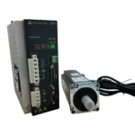
400W Braked Servo Motor Set 60ST-M01330Z1 T3L-L20F-RABN
Original price was: 750.94$.434.76$Current price is: 434.76$.
Best Quality Best Price Guarantee
In stock
🔥 Special for Today Only %42 Discount Opportunity!📦 Category: 60 mm Servo Motors and Drives🏷️ Power: 0.4 kW🏷️ Operating Voltage: 220 V AC🏷️ Flange Size: 60 mm🏷️ Brake Configuration: With External Brake🏷️ Maximum Speed: 3000 RPM
Mermak assuranceFrom factory to end user · importer / main dealer · strong stock
ImporterMain dealer / distributorStrong stockGood priceCorporate invoice
In stock / available to order · 14-day return for standard unused products; conditions may vary for custom size/cut products.
Teknik Dedaylar
What is 400W Braked Servo Motor Set 60ST-M01330Z1 T3L-L20F-RABN?
The 400W Braked Servo Motor Set 60ST-M01330Z1 T3L-L20F-RABN is a complete motion control package designed for applications requiring precise positioning and reliable load holding. This set includes the 60ST-M01330 servo motor and the T3L-L20F-RABN servo drive, specifically configured to work together in closed-loop control systems. The motor operates at a power rating of 400W (0.4 kW) with a rated torque of 1.27 Nm and a maximum speed of 3000 RPM. It features a 60 mm flange size, which is compatible with standard NEMA 23 mounting patterns, and a 14 mm shaft diameter. The system is designed for a 220V AC operating voltage and requires a current of 2.8 A. A key feature of this model is the integrated electromagnetic brake. This is a fail-safe mechanism that automatically locks the motor shaft when the power is cut or an emergency stop is triggered. This is essential for vertical axis applications where you need to prevent the load from dropping due to gravity when the system is de-energized. The brake requires a 24V DC signal to release, which must be managed by the servo drive or an external control . For feedback, the motor is equipped with a 2500 PPR (Pulses Per Revolution) incremental encoder. This provides the high-resolution position and speed data necessary for the T3L-L20F-RABN drive to perform real-time error correction. The set includes the necessary power (DL-TH-80-A10.0D) and encoder (BM-TH-80F-A10.0D) cables, typically supplied in 10-meter lengths, to connect the motor to the drive. The system is built to an IP54 protection standard, providing resistance against dust ingress and water splashes, making it suitable for standard industrial environments like CNC routers, milling machines, and automated assembly lines. When installing, ensure that the encoder cable is properly shielded and grounded to prevent electromagnetic interference, which can cause signal errors or instability in the closed-loop control. Before commissioning, verify that your control system can provide the correct pulse/direction or communication signals required by the T3L-L20F-RABN drive. If you are replacing an existing motor or integrating this into a new machine, confirm that the mechanical load inertia matches the motor's torque capacity and that your mounting setup aligns with the 60 mm flange dimensions. For specific parameter settings or wiring configurations, Mermak CNC Otomasyon provides technical support to ensure your system is correctly matched and configured for your application.
400 Watt Braked Servo Motor Set 60ST-M01330Z1 T3L-L20F-RABN
INDUSTRIAL AUTOMATION PARTS | SUPERIOR PERFORMANCE SERIES
Detailed Product Review
The 400 Watt Braked Servo Motor Set 60ST-M01330Z1 T3L-L20F-RABN is a critical electromechanical component designed for applications requiring high precision, dynamic response, and reliable performance in industrial motion control systems. This set operates on a closed-loop control principle; the integrated 2500 PPR (Pulses Per Revolution) incremental encoder continuously feeds back the instantaneous position and speed information of the motor shaft to the servo drive (T3L-L20F-RABN). The drive compares this feedback information with the target commands from the control unit, detects any deviation (error signal), and dynamically adjusts the current and voltage applied to the motor’s stator windings to ensure the shaft reaches the desired position or speed. This continuous feedback and correction mechanism enables positioning with millimeter accuracy and high repeatability. The built-in electromagnetic brake system automatically locks the shaft when the motor is de-energized or an emergency stop command is issued, preventing uncontrolled load movement, especially on vertical axes, and enhancing operational safety.
Developed in accordance with Mermak CNC engineering standards, this servo motor features a robust construction that offers uninterrupted and stable operation even in demanding industrial conditions. The motor’s housing is designed for optimal heat dissipation, maintaining thermal stability even under prolonged load. The IP54 protection class shields the motor’s internal components from harmful dust ingress and water splashes from any direction, extending the product’s lifespan and minimizing maintenance needs. The standard 60 mm x 60 mm flange size (NEMA 23 compatible) and 14 mm shaft diameter allow for easy integration with various gearboxes, couplings, and mechanical transmission systems. Supplied as a complete set, including 10-meter power and encoder cables, it simplifies system integration processes, saves engineering time, and offers an ideal solution for high-performance motion control in a wide range of industrial applications such as CNC routers, milling machines, robotic arms, automated assembly lines, and general automation equipment.
Advantages of the 400 Watt Braked Servo Motor Set 60ST-M01330Z1 T3L-L20F-RABN
Integrated Fail-Safe Brake System: The built-in electromagnetic brake in this servo motor set is a critical safety and control mechanism, ensuring the load is securely held, especially in vertical axis applications or during sudden power interruptions. This “fail-safe” design, which engages when de-energized (power-off), automatically locks the shaft when the motor’s electrical supply is cut or an emergency stop command is issued. This feature prevents the workpiece or tool from falling due to gravity, enhancing operator safety and helping to maintain machining accuracy. Applying 24V DC power from the drive or an external source is required to release the brake in a controlled manner, allowing for safe and controlled system startup and shutdown.
High-Resolution Incremental Encoder Feedback: The 60ST-M01330Z1 servo motor is equipped with an incremental encoder with a resolution of 2500 PPR (Pulses Per Revolution). This high resolution generates 2500 electrical pulses for each revolution of the motor shaft, providing highly precise positional feedback at the millimeter level in closed-loop control systems. The A/B phase signals from the encoder allow the drive to accurately perceive the motor’s instantaneous position and speed. This ensures minimal latency and maximum accuracy in communication between the drive and the control unit, which is essential for superior repeatability and machining quality in CNC machines, robotic systems, and other precision motion control applications.
Industrial Durability and Environmental Protection: This servo motor is designed to meet IP54 protection class standards. The “IP54” rating indicates that the motor’s internal mechanisms are partially protected against harmful dust ingress (the first digit ‘5’) and are resistant to water splashes from any direction (the second digit ‘4’). This feature enhances the motor’s resistance to common environmental factors in industrial settings, such as chips, metal dust, or light moisture. The robust housing structure and sealing elements protect the motor’s internal components, extending its operational life, reducing failure rates, and minimizing maintenance requirements. This environmental protection allows the motor to operate reliably and continuously even in harsh production lines.
Technical Specifications and Capacity
FeatureValue/Description
Motor Code60ST-M01330Z1
Power400 Watts (0.4 kW)
Rated Torque1.27 N·m (Newton meter)
Rated Speed3000 RPM (Revolutions Per Minute)
Encoder Type2500 PPR Incremental Encoder
Protection ClassIP54 (Protection against dust and water splashes)
Technical Frequently Asked Questions (FAQ)
How does the servo drive manage the integrated brake, and what are the critical parameters to adjust for safe operation in a vertical axis application?
The servo drive (T3L-L20F-RABN) typically manages the integrated electromagnetic brake via a dedicated control output, usually a 24V DC signal. When this signal is active, the brake coil is energized, and the motor shaft is released. Conversely, when the signal becomes inactive (e.g., during a power outage or emergency stop), the brake automatically engages, locking the shaft. Critical parameters to adjust for safe operation in a vertical axis application include the “Brake Release Delay” and “Brake Engage Delay.” The brake release delay ensures the motor develops sufficient torque before the brake is fully disengaged, preventing load drop. The brake engage delay allows the motor to decelerate to a safe speed or stop before the brake engages, preventing excessive wear or mechanical shock. Typical values range from 50-100 ms, but precise adjustment should be based on load inertia, deceleration ramps, and application safety margins. Incorrect timing can lead to premature brake wear, mechanical stress, or uncontrolled load movement.
What are the effects of using an unshielded or improperly grounded encoder cable on signal integrity, especially over long distances, for this 2500 PPR incremental encoder?
Using an unshielded or improperly grounded encoder cable for a 2500 PPR incremental encoder, particularly over distances exceeding a few meters, can cause significant signal integrity issues. Industrial environments are rich in electromagnetic interference (EMI) and radio frequency interference (RFI) generated by power cables, switching power supplies, and other electrical machinery. Without proper shielding (e.g., a braided copper shield with one end grounded, typically at the drive), this external noise can corrupt the differential A, B, and Z signals of the encoder, leading to false pulses, missing pulses, or signal distortion. This directly results in positional errors, speed fluctuations, and instability in the closed-loop control system, which can manifest as faulty machining, jerky movements, or even system failure. Improper grounding can also create ground loops, further exacerbating noise problems. For optimal performance and reliability, high-quality, shielded, twisted-pair encoder cabling and correct grounding practices are essential to maintain the integrity of high-frequency encoder signals.
How can I calculate the thermal load of the 400W servo motor in a high-cycle application, and what measures can be taken to prevent overheating beyond the IP54 protection class?
Calculating the thermal load of the 400W 60ST-M01330Z1 servo motor in a high-cycle application requires considering both continuous and intermittent torque demands, motor efficiency, and ambient temperature. The motor’s continuous thermal limit is defined by its rated power (400W) and its ability to dissipate heat. When the motor operates above its rated torque (1.27 N·m) for extended periods or during frequent acceleration/deceleration cycles,
| Power | 0.4 kW |
|---|---|
| Operating Voltage | 220 V AC |
| Flange Size | 60 mm |
| Brake Configuration | With External Brake |
| Maximum Speed | 3000 RPM |
| Torque | 1.27 Nm |
| Encoder Resolution | Incremental 2500 PPR |
You must be logged in to post a review.
Taksit Tablosu
What is 400W Braked Servo Motor Set 60ST-M01330Z1 T3L-L20F-RABN?
The 400W Braked Servo Motor Set 60ST-M01330Z1 T3L-L20F-RABN is a complete motion control package designed for applications requiring precise positioning and reliable load holding. This set includes the 60ST-M01330 servo motor and the T3L-L20F-RABN servo drive, specifically configured to work together in closed-loop control systems. The motor operates at a power rating of 400W (0.4 kW) with a rated torque of 1.27 Nm and a maximum speed of 3000 RPM. It features a 60 mm flange size, which is compatible with standard NEMA 23 mounting patterns, and a 14 mm shaft diameter. The system is designed for a 220V AC operating voltage and requires a current of 2.8 A. A key feature of this model is the integrated electromagnetic brake. This is a fail-safe mechanism that automatically locks the motor shaft when the power is cut or an emergency stop is triggered. This is essential for vertical axis applications where you need to prevent the load from dropping due to gravity when the system is de-energized. The brake requires a 24V DC signal to release, which must be managed by the servo drive or an external control . For feedback, the motor is equipped with a 2500 PPR (Pulses Per Revolution) incremental encoder. This provides the high-resolution position and speed data necessary for the T3L-L20F-RABN drive to perform real-time error correction. The set includes the necessary power (DL-TH-80-A10.0D) and encoder (BM-TH-80F-A10.0D) cables, typically supplied in 10-meter lengths, to connect the motor to the drive. The system is built to an IP54 protection standard, providing resistance against dust ingress and water splashes, making it suitable for standard industrial environments like CNC routers, milling machines, and automated assembly lines. When installing, ensure that the encoder cable is properly shielded and grounded to prevent electromagnetic interference, which can cause signal errors or instability in the closed-loop control. Before commissioning, verify that your control system can provide the correct pulse/direction or communication signals required by the T3L-L20F-RABN drive. If you are replacing an existing motor or integrating this into a new machine, confirm that the mechanical load inertia matches the motor's torque capacity and that your mounting setup aligns with the 60 mm flange dimensions. For specific parameter settings or wiring configurations, Mermak CNC Otomasyon provides technical support to ensure your system is correctly matched and configured for your application.
Related Products
 %42 Discount750W Braked Servo Motor Set 80ST-M02430Z1 T3L-L20F-RABNOriginal price was: 757.28$.438.43$Current price is: 438.43$.View
 %42 Discount2 kW Braked Servo Motor Kit 130ST-M07725Z1 T3A-L30F-RABFOriginal price was: 1,211.63$.701.47$Current price is: 701.47$.View
 %40 Discount2 kW Servo Motor Set 130ST-M07725 T3A-L30F-RABFOriginal price was: 939.98$.565.97$Current price is: 565.97$.View
Reviews
There are no reviews yet.