
No products in the cart.
%42 Discount


1 kW Braked Servo Motor Kit 80ST-M04025Z1 T3L-L20F-RABN
Original price was: 860.33$.498.08$Current price is: 498.08$.
Best Quality, Best Price Guarantee
In stock
🔥 Special for Today Only %42 Discount Opportunity!📦 Category: 80 Flange Servo Motors🏷️ Power: 1 kW🏷️ Operating Voltage: 220 V AC🏷️ Flange Size: 80 mm🏷️ Brake Configuration: With External Brake🏷️ Maximum Speed: 2500 RPM
Mermak assuranceFrom factory to end user · importer / main dealer · strong stock
ImporterMain dealer / distributorStrong stockGood priceCorporate invoice
In stock / available to order · 14-day return for standard unused products; conditions may vary for custom size/cut products.
1 kW Braked Servo Motor Kit 80ST-M04025Z1 T3L-L20F-RABN
INDUSTRIAL AUTOMATION PARTS | SUPERIOR PERFORMANCE SERIES
Detailed Product Review
This 1 kW braked servo motor kit is a closed-loop drive system designed to provide high-precision positioning, speed, and torque control in industrial automation systems. Its fundamental operating principle involves receiving feedback through an incremental encoder that continuously monitors the motor’s rotor position and speed, transmitting this information to the servo drive. The servo drive generates an error signal by comparing the reference command signals (typically position, speed, or torque commands) from the controller with the real-time feedback signals from the encoder. This error signal is processed by the drive’s PID (Proportional-Integral-Derivative) or more advanced control algorithms (e.g., Field-Oriented Control – FOC) to dynamically adjust the current and voltage applied to the motor’s stator windings. This ensures the motor reaches its desired position with micrometer accuracy, rotates at a set speed with constant torque, and responds instantly to external load variations. The integrated electromagnetic brake mechanism, particularly in vertical axis applications or systems requiring load holding, instantly locks the motor shaft in case of power failure or emergency stop, preventing uncontrolled load descent or position loss. The brake is a spring-applied, fail-safe mechanism that engages when de-energized and is released when energized by a DC 22-28V (nominal 24V) supply, overcoming the spring force with an electromagnet to disengage friction discs, significantly enhancing operational safety and system integrity.
The motor housing is typically manufactured from high-strength aluminum alloys using precision machining techniques to optimize heat dissipation and provide high resistance against mechanical stresses, vibrations, and environmental factors in industrial settings. Its internal structure features Neodymium-Iron-Boron (NdFeB) permanent magnets for high energy density and efficiency, along with optimized low-resistance copper windings. The 80 mm flange size allows for easy integration with standard industrial mounting interfaces (e.g., gearboxes, linear actuators, or direct machine chassis) in accordance with ISO standards. System integration is achieved by connecting the servo drive to a PLC (Programmable Logic Controller), CNC control board, or robot controller via digital signals (e.g., pulse/direction, EtherCAT, PROFINET, CANopen) or analog signals. The power cable has conductors of appropriate cross-section to meet the motor’s 1 kW continuous power requirements and separate DC 24V supply connections for the electromagnetic brake, while the encoder cable is shielded against industrial electromagnetic interference (EMI/RFI) and typically supports differential signal transmission (RS422), guaranteeing reliable and error-free transmission of precise feedback signals. This kit is preferred in critical industrial applications such as preventing slippage on the Z-axis of CNC routers due to spindle motor weight, processing parts with millimeter precision in automatic cutting machines, ensuring robotic arms remain stable under load at specific positions, preventing load rollback on inclined conveyor systems, and creating repeatable motion profiles in precision assembly lines.
Advantages of the 1 kW Braked Servo Motor Kit 80ST-M04025Z1 T3L-L20F-RABN
Integrated Electromagnetic Brake System: This servo motor kit is equipped with an internal electromagnetic brake mechanism. This brake operates on a “fail-safe” principle; meaning, when the electrical supply is cut off or an emergency stop command is issued, it automatically engages via spring force, mechanically locking the motor shaft. This feature is crucial in applications where gravity is a significant factor, such as the Z-axis of CNC machines, vertical transport systems, robotic manipulators, or elevator mechanisms, definitively preventing uncontrolled downward slippage or falling of the load. Released when the electromagnet overcomes the spring force by being supplied with DC 24V, this brake maximizes operational safety, ensures position holding even during power outages, and prevents potential workpiece damage, machine malfunctions, or operator injuries. Furthermore, the motor’s ability to maintain its position when stopped eliminates the need for an external locking mechanism, simplifying system design and reducing costs, while also allowing for more compact machine designs.
High Dynamic Performance and Precision: With a 1 kW continuous power capacity, 4 Nm nominal torque, and 12 Nm maximum torque, this servo motor kit offers the rapid acceleration and deceleration capabilities required by industrial applications. A nominal speed of 3000 RPM provides sufficient dynamic range for applications requiring high-speed motion profiles and short cycle times. The 2500 PPR (Pulses Per Revolution) incremental encoder provides high-resolution position information for each revolution of the motor shaft, enabling the servo drive to achieve millimeter or micrometer precision positioning and smooth speed control through its closed-loop control algorithm. The 4x resolution enhancement (10,000 counts/revolution) obtained from the 90-degree phase difference between A/B phases in square-wave output encoders ensures that even the smallest motion changes are detected and corrected. This combination delivers superior motion control performance that directly impacts repeatability, product quality, and production efficiency, especially in precision machining, cutting, assembly, or inspection operations, thereby allowing for tighter production tolerances and reduced scrap rates.
Optimized Efficiency and Thermal Management: Compliant with Mermak CNC corporate design codes, this kit exhibits high energy efficiency due to the perfect synchronization between the motor and drive, and advanced control algorithms. Advanced servo drive algorithms (e.g., Field-Oriented Control – FOC) minimize copper and iron losses in the motor windings, while the motor’s optimized magnetic circuit and low-resistance windings minimize heat generation. This thermal management ensures the motor maintains stable operating temperatures even under continuous nominal load for extended periods. Lower heat generation extends the lifespan of the motor and drive’s insulation materials and mechanical components (such as bearings), reduces maintenance requirements, and directly contributes to lower operating costs by reducing energy consumption. Furthermore, stable operating temperatures guarantee that the motor’s magnetic properties and electrical parameters remain unchanged over time, enhancing the overall reliability and performance consistency of the system. This is critically important in industrial environments requiring high duty cycles and continuous operation, preventing failures caused by thermal stress.
Technical Specifications and Capacity
Feature
Value/Description
Power Capacity
1.0 kW (1000 Watts) Continuous Output Power
Nominal Torque
4.0 Nm (Continuous torque output at nominal speed)
Maximum Torque
12.0 Nm (Short-term acceleration/deceleration torque, 3x nominal)
Nominal Speed
3000 RPM (Revolutions per minute, continuous operating speed)
Supply Voltage
AC 220V (Motor main power supply) / DC 24V (For brake activation)
Flange Size
80 mm (Industrial standard mounting interface, IEC compliant)
Encoder Type
2500 PPR Incremental (High-resolution position feedback)
Technical Frequently Asked Questions (FAQ)
Why is inertia matching a critical factor for optimizing the performance of this servo motor kit, and what are the ideal ratios?
Inertia matching refers to the ratio between the inertia of the servo motor’s rotor and the inertia of the load it drives, directly impacting the system’s dynamic response, stability, and energy efficiency. Ideal inertia matching is necessary to ensure stable operation of the control loop, rapid acceleration and deceleration capabilities, and precise positioning accuracy. When the load inertia is too low relative to the motor inertia (e.g., less than 1:1), the system can become overly sensitive, prone to oscillations from minor perturbations, and difficult to tune for higher control loop gains. Conversely, when the load inertia is too high relative to the motor inertia (e.g., greater than 10:1), the motor’s ability to effectively control the load diminishes, acceleration and deceleration times increase, leading to longer cycle times and higher energy consumption. Furthermore, high inertia ratios can cause excessive stress and vibrations in the mechanical system, shortening machine life. For general industrial applications, inertia ratios between 1:1 and 5:1 typically offer an acceptable balance; however, for applications requiring very high precision or dynamics, ratios close to 1:1 are targeted. To achieve optimal performance from this motor kit, it is critical during the system design phase to appropriately match the load inertia to the motor inertia through the selection of gearbox ratios and mechanical components, along with proper tuning of the servo drive’s PID gains and effective use of resonance filters.
What considerations must be taken into account for electromagnetic compatibility (EMC) when selecting and installing the power and encoder cables for this servo motor kit?
Electromagnetic compatibility (EMC) is vital for the reliable and error-free operation of servo motor systems in industrial environments. The selection and installation of power and encoder cables must adhere to specific engineering principles to both reduce electromagnetic emissions (EMI) and enhance electromagnetic immunity (EMS). For power cables, shielded cables of appropriate cross-section and low inductance should be preferred to meet the motor’s 1 kW continuous power requirement. Shielding prevents high-frequency switching noise from the motor drive from radiating into the surroundings. Encoder cables, carrying precise low-voltage signals for motor position and speed feedback, must be highly shielded and typically feature a twisted-pair construction. Twisted pairs cancel common-mode noise in differential signal transmission, preserving signal integrity. During installation, routing power and signal cables in separate conduits or maintaining a minimum distance of 30 cm, minimizing parallel runs, and crossing signal cables over power cables at 90-degree angles reduces EMI induction. Grounding the cable shields at both ends (motor and drive side) with low impedance (using 360-degree grounding clamps) provides a path for high-frequency noise currents, maximizing shielding effectiveness. Additionally, using ferrite beads at cable entry points can dampen high-frequency noise. These practices ensure the system’s compliance with EMC standards (e.g., EN 61800-3), minimize interference with other electronic equipment, and guarantee the stable operation of the servo system.
How is the Safe Torque Off (STO) safety function found in servo drives integrated with this motor kit, and what is its importance in industrial safety?
Safe Torque Off (STO) is a fundamental safety function used in industrial automation systems for safely stopping servo motors, designed in accordance with relevant safety standards like IEC 61800-5-2. This function hardware-disables the power supply to the motor windings, preventing the motor from generating torque and thus preventing unexpected restarts or movement. Integration with this 1 kW braked servo motor kit typically involves connecting a signal controlled by a safety relay or safety PLC to the STO input terminals of the servo drive. The safety controller activates the STO input upon receiving a trigger signal from a safety device such as an emergency stop button, safety door sensor, or light curtain. This disables the power switching elements (IGBTs) in the drive’s output stage, cutting off current to the motor windings. The motor’s internal brake engages automatically in this situation, providing mechanical locking and holding the load’s position. The importance of STO in industrial safety is significant because: (1) It ensures safety for machine operators or maintenance personnel when accessing hazardous moving parts. (2) It prevents uncontrolled movements during machine malfunctions or unexpected situations. (3) It forms the basis for more complex safety functions (e.g., Safe Stop 1 – SS1, Safe Operating Stop – SOS). STO stops hazardous movements by cutting motor power while allowing the system’s control circuit to remain energized, enabling a quick restart and minimizing production downtime.
How does the auto-tuning feature in servo drives optimize the performance of this motor kit, and which parameters does it affect?
The auto-tuning feature is an advanced function in modern servo drives used to automatically analyze the dynamic characteristics of the motor and connected mechanical system to optimize control loop parameters. This feature significantly simplifies installation and commissioning processes and reduces the need for manual tuning. When used with this 1 kW servo motor kit, the auto-tuning process typically begins with the drive sending specific test signals (e.g., step response or frequency sweep) to the motor and analyzing the feedback signals received from the encoder. Using this data, the drive determines the system’s inertia, friction coefficients, stiffness, and resonant frequencies. Based on this analysis, the drive automatically adjusts the following key control parameters: (1) PID Gains: Proportional (P), Integral (I), and Derivative (D) gains are adjusted to optimize the response time, stability, and error tolerance of the position, speed, and torque loops. (2) Filters: Various digital filters, such as notch filters, low-pass filters, and vibration suppression filters, are automatically set to suppress mechanical resonances and reduce signal noise. (3) Feedforward Parameters: Torque and speed feedforward parameters are optimized for faster and smoother responses to load variations or acceleration/deceleration commands. Auto-tuning enables the system to reach its target position quickly without excessive oscillation, become more resistant to load changes, and exhibit smoother motion profiles. This improves overall machine efficiency, tightens production tolerances, and extends the motor’s lifespan.
| Power | 1 kW |
|---|---|
| Operating Voltage | 220 V AC |
| Flange Size | 80 mm |
| Brake Configuration | With External Brake |
| Maximum Speed | 2500 RPM |
| Torque | 4 Nm |
| Encoder Resolution | Incremental 2500 PPR |
You must be logged in to post a review.
Taksit Tablosu
Related Products
 %42 Discount750W Braked Servo Motor Set 80ST-M02430Z1 T3L-L20F-RABNOriginal price was: 757.28$.438.43$Current price is: 438.43$.View
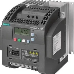 %68 Discount5.5 kW Variable Speed Drive - Siemens 380VOriginal price was: 1,342.30$.433.44$Current price is: 433.44$.View
 %68 Discount1.1 kW Siemens Sinamics V20 Variable Frequency Drive (VFD) - 220V Single Phase InputOriginal price was: 410.35$.132.48$Current price is: 132.48$.View
Reviews
There are no reviews yet.